Continue to Site

Welcome to our site!

Electro Tech is an online community (with over 170,000 members) who enjoy talking about and building electronic circuits, projects and gadgets. To participate you need to register. Registration is free. Click here to register now.

  • Welcome to our site! Electro Tech is an online community (with over 170,000 members) who enjoy talking about and building electronic circuits, projects and gadgets. To participate you need to register. Registration is free. Click here to register now.

what's best to read ESR with a microchip ADC

Status
Not open for further replies.
Thanks Nigel Goodwin I'm making some test gear my scope looks lonely LOL. You had posted some where on a strip board layout tool if not to much trouble could you post it here. I looked at some on the net not as good as the one you posted. Guess i can forget the 1.1 on the Vref+ pin LOL
2.5 it is cause 1.8 is as low as she goes.
 
Last edited:
Haha I seen that I'm wanting the software to layout strip board you posted a link I downloaded but my server hard drive died and lost a bunch of my stuff I did good thing is I posted so much junk on the net I can Google me and find most stuff
 
Hello again,

Thanks for the pdf.

So it appears that they are all working on the idea that if the frequency is high enough, then the voltage developed across the ESR resistance is much higher than the voltage developed across the internal capacitance. If we want that to be at a ratio of 10:1 for good measure, then we would want to enforce the rule:
w>10/(R*C)

where R is the expected ESR resistance and C is the expected capacitor value.

This is interesting because if we use a sine wave then we have to follow that rule pretty strictly or we wont get readings that make much sense with different capacitor values.
Using a square wave we have the benefit of the higher harmonics which improves the ratio a bit, but how much should probably be investigated. With the third harmonic being 1/3 of the fundamental, that means we do get at least three times the frequency if the wave front and back are both sharp. We might reduce the requirement, but then we probably have to filter out the fundamental.

For R=1 and C=100uf we get:
w>10/(0.0001)=100000
so f is close to: 16kHz.

With R=0.1 and C=100uf, we get:
w>10/0.00001=1000000
so f is close to: 160kHz.

With R=0.01 and C=100uf, we get:
w>10/0.000001=10e6
so f is close to 1.6Mhz

however with R=0.01 and C=1000uf, we get:
w>10/0.0001=1000000
so f is close to: 160kHz again.

This seems to show that capacitors of 1000uf or better will show best results and caps lower like 100uf will not show good readings unless the ESR is somewhat high, like 1 ohm.

This deserves more looking into however as i just took a quick cursory glance at how this might work out. Perhaps people might quote some actual real life measurements and how accurate they think they are.

I also see a small capacitor coming into play to swamp effects from any possible series ESL which is the small series inductance that could be present. I am not as worried about this right now though.

A BIT LATER:
After reading my own post (har har) i realized that if we test using two different frequencies we can tell if we are at a frequency that is acceptable for the test. If at F1 we see 1v, then at F2 we see 0.5v, we still are not at the right frequency. If we test at a third frequency F3 and see 0.490, we are probably at a frequency that is acceptable for the test. Thus, we just keep increasing the frequency until we reach a point where the result voltage amplitude does not go down much.
 
Last edited:
I did a quick simulation of 1000uf with 0.030 ohm ESR. Waveform attached. The source is again a plus and minus 4v square wave, and the added series resistance for the test was 600 ohms.

This is certainly a simple method with a scope.
The Step voltage is a result of the ESR in the Cap, which in this case is 0.4V out of 4.0V pp or 10% and thus 10% of 600 Ohms or 60 Ohms.

Using the ESR*C figure of merit, this cap is 1000u*60 = 60ms which is a good result. ( 1ms best... 1 second is poor)
 
Hi Willen,
Theres little diffrence between the ludens schematic and the one you posted, in fact the ludens one has less parts, the osc and the amp are in one 8 pin chip, not having a transistor theres little in the way of biasing resistors.
The scale on mine starts at 30 ohm, going to 2 ohms 1/2 way, and the last quater way is 1 ohm, so you can read down to a fraction of an ohm, the only thing with a log scale is that you couldnt resolve 10 ohm from 10.5 ohm, however its more than acceptable for repair work, I dont read resistance the diffrence between a good and bad cap is usually large, tens of ohms.
Hi dr pepper,

I have 500uA cheap VU meter instead of 50uA sensitive meter so I had to decrease down the emitter resistor to 33 ohms to get full scale on the meter. It can display approx 60 ohms as full scale. It shows 22 ohms in 1/2 way. Difference between 0 ohm and 1 ohms is just 2 or 3% of the display. Maybe your has 50uA nice meter. So you got nice resolution (long run way) around 1 ohm. So nice!

However as you said if the difference ES-Resistance between 1000uF damaged capacitor and 1000uF well condition capacitor is like 10 ohms then I can decide the failure. I saw some typical chart of uF versus ESR so they wrote like this way (value are just an example)-

1000uF--> High Quality 0.02 ohms---Normal 0.1 ohms---Poor 0.8 ohms

But they don't listed 'damaged' so maybe I need to find five or ten ohms to conform that the capacitor has been damaged.
 
Last edited:
This is certainly a simple method with a scope.
The Step voltage is a result of the ESR in the Cap, which in this case is 0.4V out of 4.0V pp or 10% and thus 10% of 600 Ohms or 60 Ohms.

Using the ESR*C figure of merit, this cap is 1000u*60 = 60ms which is a good result. ( 1ms best... 1 second is poor)

Hi Tony,

Sorry, but i dont understand what you are trying to say here.
The graph i had shown shows a total wave amplitude of less than 2mv, and the ESR amplitude is only about 1/5 of that (estimate) which means it is only about 0.0004v and at 8v/600 amps current change that means we have ESR that is:
ESR=0.0004/(8/600)=0.030 ohms.
We have to use 8/600 instead of 4/600 because the current changes from +4/600 to -4/600 which is a total change of 8/600, and that leads to the correct ESR.
I guess you were also working in millivolts intead of volts which makes sense.
 
My attention to units failed.
step change on output 0.4mV ?? my mistake
step input = 4V
Rs= 600 Ohms
step attenuation = 4V/0.4mV = 10,000

if you add both input current steps + and -
then you have to add both output steps.

So dont.

So you input is only a 4V step not 8V

And my mistake output scale was mV

ESR = 600/10,000 = 60 mΩ

did I get it right this time?
 
Hi willen,
I think I used germanium diodes in the rectifier, must have made a difrence, with the ludens circuit you could probably put the diodes in the feedback loop of the op amp and get zero drop.
Adjusting r8 woudl probably make the same diffrence.
 
That looks like a good design Nige, what did you use for the bulb?, I used to have some ra53 thermistors which were pretty much exclusively for wien osc's, but they've all long gone.
 
My attention to units failed.
step change on output 0.4mV ?? my mistake
step input = 4V
Rs= 600 Ohms
step attenuation = 4V/0.4mV = 10,000

if you add both input current steps + and -
then you have to add both output steps.

So dont.

So you input is only a 4V step not 8V

And my mistake output scale was mV

ESR = 600/10,000 = 60 mΩ

did I get it right this time?

Hi,

Thanks for the reply.

Well, if you look at the voltage waveform in the post with that wave, looking at the very peak of the wave we can approximate that is 2mv. That means at that point (and because the voltage is so low) we can approximate the current at the top to +4/600 amps because of the input voltage at that time is +4v and the resistance is 600 ohms. The next thing that happens is the input switches from +4v to -4v, and that means the current is now -4/600 amps, and a nanosecond later the voltage goes from +2mv to +1.6mv (estimate), and the current required to force that change was 8/600 amps. To look at it another way, the ESR resistance is 'biased' by +4/600 amps at the very tip of the wave, then 'biased' by -4/600 amps at the lower point maybe 1 nano second later (at the bottom of the steep drop). So the resistor is first biased positively and then negatively, it does not hover at 0 amps for any real length of time (maybe 0.1 nanosecond). If we did look at that point in time, we would see a point in the steep voltage drop that is 1/2 the way down to where it starts to ramp rather than at the very bottom of the steep ramp.

What else helps to visualize is to graph the current along with the voltage, which i didnt do unfortunately. That way we see the current change rather than the absolute current value. Doing that would show a current of +4/600 amps at the very topmost point and -4/600 amps at the very lowest point of the steep slope which is the start of the downward ramp.

One other thing i should point out is that if we do a simulation with a capacitor in series with a 30mOhm resistor and using a square wave of plus and minus 4 volts we get that exact waveform. If we double the resistor value to 60mOhms then we see twice the change before the downward ramp starts, so instead of about 0.0004v we would see 0.0008v there.

The attachment shows the waveform with 60mOhms of ESR.
 

Attachments

  • CapESR_Test-02.gif
    CapESR_Test-02.gif
    11.3 KB · Views: 165
Last edited:
That looks like a good design Nige, what did you use for the bulb?, I used to have some ra53 thermistors which were pretty much exclusively for wien osc's, but they've all long gone.

I used a little wire ended bulb, as in the article - except I bought mine from RS Components not Maplin - just checked on Maplin, the original is still listed.
 
I remember wanting to use a rugged bulb for a PTC current limiter before PTC current limiters were invented for a telemetry application.
As they rise in temperature, they make good current regulators, since the tungsten resistance increase 10 fold from cold to hot.

Even though the bulb would last a long time running cool, it wasn't reliable enough.

BTW thanks AL or rather MrAl
I got it now....

Using a sufficiently high f square wave then there is no time for the cap to charge up.
then it is plain to see the Voltage ratio from input to output is 4Vpp/200uVpp = 2000
so ESR is 600/2000=30mΩ
upload_2015-8-20_13-2-18.png


This is an easy method to check when there is ripple on a SMPS in circuit with excessive ESR . Although too low and some LDO's can go unstable, with too low a voltage feedback as the ESR*C time constant gets too low and causes phase shift in the feedback voltage with ultralow RdsOn type LDO's
 
Last edited:
Hi Tony,

Yeah some LDO's are a bit fussy with the ESR of the cap. Regular style boost converters can have this problem too, as an ESR that is too low can cause instability there too.

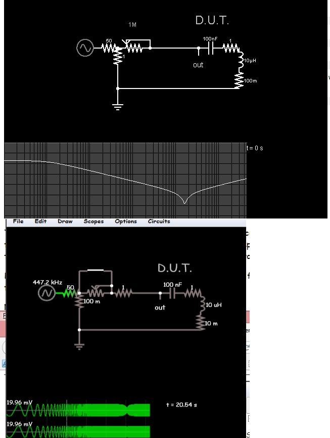
So i guess we have established that the main operating principle of the ESR meters is to measure the AC voltage across the cap with an AC current frequency that is high enough to keep the voltage from the capacitance from influencing the AC voltage measurement by too much. The mathematics shows that a frequency of w>10/RC should be employed in order to keep the voltage across the capacitive part low, leaving mostly the voltage across the ESR to be measured.

With many measurements however it is often possible to come up with a bridge type balanced condition that allows accurate measurement of the quantity in question. This makes me wonder if there might be a way to do this for the ESR too.
For a simple but unusual example, which i hope i am quoting correctly here, goes like this: we use a small series resistor this time, one as small as we expect the ESR to be, in series with the cap, and we apply an AC voltage to the network and measure the AC voltage across the cap. We adjust the small series resistance and the voltage source until we get exactly 1/sqrt(2) volts across the cap (about 0.707vac) and a phase shift of 2.25 degrees from input to output (output is voltage across the cap). When the voltage is 0.707 and the phase shift is 2.25 degrees then the series resistance is the same as the ESR.
The only problem with this method is that it is not that easy to measure 2.25 degrees that accurately, but you get the picture. We try to find a way to adjust a reference value until we reach some condition that is easy to measure, especially a zero in some quantity like voltage or current. There is probably a good way to do this.

Yeah the scope method works pretty well if you have a scope and a wave generator or at least a square wave oscillator.

We could probably look at other methods too, such as driving with two different currents I1 and I2 at the two different frequencies w1 and w2 respectively, the ESR is then:
ESR=sqrt(-w1^2*I2^2+w2^2*I1^2+(v2^2-v1^2)*w1^2*w2^2*C1^2)/(w1*w2*C1*sqrt(I2-I1)*sqrt(I2+I1))

or simplified:
ESR=(I1^2*W+(v2^2-v1^2)*w*C1^2*W-w*I2^2)/(w*C1^2*(I2-I1)*(I2+I1)*W)

where W is w2^2 and w is w1^2, or better yet:

ESR^2=-(v1^2*w1^2*I2^2-v2^2*w2^2*I1^2)/((w2^2-w1^2)*I1^2*I2^2)

C^2=((w2^2-w1^2)*I1^2*I2^2)/(v1^2*w1^2*w2^2*I2^2-v2^2*w1^2*w2^2*I1^2)

If we can get I2=I1 by adjusting the second voltage source, then this simplifies even more to:

ESR^2=(v2^2*w2^2-v1^2*w1^2)/((w2^2-w1^2)*I1^2)

C^2=((w1^2-w2^2)*I1^2)/((v2^2-v1^2)*w1^2*w2^2)
 
Last edited:
high 5 for your formulae. ^5

Any 5V CMOS clock @50 Ohms ESR or so will work with a series R if one doesn't have a Sig. Gen.

Or Sig Gen with FM input for measuring DUT input impedance.
2338616800_1440096668.jpg


Getting back to OP's question, it would be easy to generate a 1MHz CMOS clock with a larger Series R as CMOS outputs are close to either 25 or 50 Ohms depending on type of CMOS, THen measure the square wave Vpp with a precision OP AMp diode rectifier with gain then input an ADC to measure the resulting square wave at a slow conversion rate.
 
Last edited:
I only use CPC, RS and Farnell, and sometimes ebay.
 
Dunno.
I have an account with farnell and an account with CPC, I also have my own personal non works cash account with CPC, which is close enough for me to go on my pushhog, CPC were takien over by farnell, I used to go to CPC back in the 80's when they had their really small place up town and hadnt been in business long.
Interestingly the building they took over was serviscope, a large tv repairs centre.
 
Status
Not open for further replies.

Latest threads

New Articles From Microcontroller Tips

Back
Top