Continue to Site

Welcome to our site!

Electro Tech is an online community (with over 170,000 members) who enjoy talking about and building electronic circuits, projects and gadgets. To participate you need to register. Registration is free. Click here to register now.

  • Welcome to our site! Electro Tech is an online community (with over 170,000 members) who enjoy talking about and building electronic circuits, projects and gadgets. To participate you need to register. Registration is free. Click here to register now.

Using a mouse optical encoder

Status
Not open for further replies.

shehry

New Member
hi,

i was trying to use the digital optical encoder in a mouse to calculate the rpm of my motor. i was trying to see what kind of output do the IR sensors send to the mouse controller em84510ep. but giving common ground to the oscilloscope tends to hang the mouse.

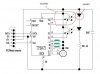
does anyone know how to use the ir sensors in a mouse. the mouse has a white and black transmitter and receiver. the transmitter has two pins and the receiver has three.

now two pins (one each of transmitter and receiver) are connected to gnd. the other pin of the transmitter is connected to the mouse controller via a resistor. and the remaining two pins of the receiver are connected to X1 and X2 of the controller.

can anyone help
 

Attachments

  • em84510ep_mouse_controller.pdf
    108.3 KB · Views: 4,383
I can't see your pdf for whatever reason???

The mouse has probably 'hung' because you have effectively grounded the control signals through the common eath connection between PC and scope. You will need to isolate the oscilloscope or PC earth to make any readings? - Just realise any safety / static etc... implications if doing this! - Do you have an isolation transformer - somthing to consider if you own a scope!!!
Can you not attach an external (5V?) supply to the mouse while not attached to the computer?

The sensor is a twin jobby with common junctions hence three leads - how do you think the mouse knows which way you want to move the cursor???
 
simplest and safest way to fix your scope is to use isolating transformer but you might opt to just remove ground pin from the ac plug.
as for mouse, it's simply consisting of two quadrature encoders (one for vertical and other for horizontal movement of the mouse).
sender is one led (not nececarily visible light) which is two wire device.
on the other end you have two receivers (photo transistors for example).
this is why there are three wires (one is common). i'm sure you will find tons of examples on how quadrature encoders work or how to use them.
in fact it's very simple. led shines light at two receivers. when encoder disc (wheel with holes for example) moves in between, you can count pulses and measure position. the nice thing with quadrature is (this is why you need two receivers per channel) that you can determine direction of rotation (often just using pair of D-flip-flops). this means that you will know position very precisely even if encoder wheel vibrates in position. without quadrature, your counter would go loco and keep on counting.

**broken link removed**
http://www.armory.com/~rstevew/Public/Motors/Quadrature/Dig_Knobs.gif
http://www.armory.com/~rstevew/Public/Motors/Quadrature/QuadDecoderCounter.gif
 
i disconnected the ir receiver and transmitter from the mouse and placed them on the bread board. the ckt was something like this. the thing on the left is the transmitter. on the right is the receiver.

+5 ---(500 ohm)-----|__ __
gnd -------------------|__| |__|---------gnd
| |
| |------------(output)
(1 Kohm)
|
+5

i think that this circuit should work. but it doesnt. whether obstructed or not, the output is a constant high no matter what. i left the 3rd pin of the receiver open because all i need to calculate is the revolutions not the direction. most probably the bias resistor of the receiver is too low and pulls the output to a high.

can anyone guide?
 
aww cmon.... you have to do better than that...
either use Code button or paste as picture.
i just found one old pcb of what used to be wheel mouse so it has
three sets of sensors.
emitter is just clear LED. electrodes inside it are different length.
shorter one is anode according to silkscreen and orientation of caps.
receiver (3-wire thingy) has middle pin connected to V+ (and pin1 of the chip) while the two other pins (quadrature outputs) go to chip which is obviously controller.
Google helped in finding datasheet for TP8472BP (pins 12,13 for one axis, 14,15 for second and 3,4 for wheel):
**broken link removed**
 
after glancing datasheet, i've found diagram on page 21 of 23 that shows what i suspected all along - receiver is pair of NPN transistors with common collector.
 

Attachments

  • mouse.jpg
    mouse.jpg
    33.2 KB · Views: 13,028
Status
Not open for further replies.

Latest threads

New Articles From Microcontroller Tips

Back
Top