Continue to Site

Welcome to our site!

Electro Tech is an online community (with over 170,000 members) who enjoy talking about and building electronic circuits, projects and gadgets. To participate you need to register. Registration is free. Click here to register now.

  • Welcome to our site! Electro Tech is an online community (with over 170,000 members) who enjoy talking about and building electronic circuits, projects and gadgets. To participate you need to register. Registration is free. Click here to register now.

urgent help needed for PS

Status
Not open for further replies.
You don't need to "join anything" for a higher output current.
The LM317 has a max current of 1.5A.
The LM350 has a max current of 3A.
The LM338 has a max current of 5A.
They will work if your supply voltage is not so high.

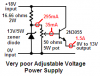
The 3.125 ohm resistor sets the max current to only 400mA.
If it is 0.833 ohms then the max current is 1.5A.
If it is 0.417 ohms then the max current is 3A.
If it is 0.25 ohms then the max current is 5A.
 
Last edited:
Can i ask one last favor.
Can anyone please design me a power supply using a power transistor (NPN or PNP) and zener diode, for the same variable 12volts output bearing upto some 1a to 1.5A...
and if possible then list all components required wattage.
(but please give alternates to high watt-ed component like i couldn't find 5watt zener diode.. the highest rated zener found around here is 2watts)

please, i'd be grateful.
 
This thread is going around in circles.

Lets be quite clear:

A 0 to 12v regulated power supply CANNOT be made with one transistor, one zener diode and a bunch of resistors.

A fixed voltage supply with poor regulation CAN be made with one transistor, one zener diode and a bunch of resistors.

You stated your project requirements:
0 to 12v regulated
1 amp output current

You stated your resources which included an LM317.

I provided you with:
the basis of a solution using an LM317
a work around for un-available components

You are now still trying to make a silk purse out of the pigs ear of your original flawed circuit.

What is your problem?

JimB
 
You can make a very poor 0V to 12V power supply with a 2N3055 transistor, a very high power 13V zener diode, a very high power resistor and a very high power low resistance potentiometer.

It makes a lot of heat is it is unloaded or if it is loaded.
Its output voltage is not regulated:
1) Its max output is 12.3V without a load and drops to about 11V at 1.5A.
2) Its half output is 5.8V without a load and drops to about 3.8V at 1.5A.
 

Attachments

  • poor power supply.PNG
    poor power supply.PNG
    9.1 KB · Views: 92
does the wattage increases if 5, 13volt 1watt zener are connected in parallel..
i mean that happens with resistors... but wht about zener diodes.
 
and i am suppose to submit in a transistor power supply... only thats why i am making that as well.. other wise i had no mood to do it...
Thanks JimB and AudioGuru.
 
burhanmz said:
does the wattage increases if 5, 13volt 1watt zener are connected in parallel..

If and only if the diodes are perfectly matched, which in a practical situation they will not be.
The one with the lowest zener voltage will take the most current and eventually burn up, then the next lowest, then the next... and so on until the last one expires in a puff of smoke and makes its way to silicon heaven.

JimB
 
Add a transistor to the poor power supply then the zener diode can be a small one and the resistor and pot can also be small.
The output will not change as much when the load current changes and it can be adjusted from 0V to at least 13V at up to 1.5A.
 

Attachments

  • better power supply.PNG
    better power supply.PNG
    15.5 KB · Views: 96
oh, i never meant to say that i'm not supposed to use 2 or more transistors... so AudioGuru thats Darligton pair... Can i instead use BD679, the shopkeeper said it will fulfill my requirement, is that so?

can you please add me in your msn messenger list or yahoo messenger, AudioGuru and Jimb... please i just want to ask few other things... if u want u can delete me from ur list after that... my email is

burhanmz@msn.com
burhanmz@yahoo.com
 
A BD679 darlington transistor will work fine in that power supply circuit. It is small so it will need a pretty big heatsink.
The circuit is not regulated, its output voltage changes when the load current changes. Is that OK?
 
can please define this diagram and give the calculations and working of BD679...
please...

have made two power supplies on is with LM317T and this BD679...
thanks JimB and AudioGuru.

*got this circuit from yahoo answers!
 

Attachments

  • 2-amp-circuit.gif
    2-amp-circuit.gif
    6.8 KB · Views: 147
i have made changes in above diagram,
1. bridge IC rated 3A
2.instead of 470:eek:hm: , i am using 1000:eek:hm: 2W resistor
3. the pot is 10k:eek:hm: rated 5W
4. inserted a 1000:eek:hm: in series with led whole parallel with capacitor 2.2mF, as an indicator..

please give calculations and working of BD679... i have to submit it tomorrow and have to explain it as well.
 
For your new circuit:
Calculate the power dissipated in the 1k resistor. It is only 0.023W. You don't need a huge 2W resistor.
Calculate the power dissipated in your 10k pot. It is also only 0.023W. You don't need a huge 5W pot.

What else needs to be calculated?
The BD679 has a minimum current gain of 750 so at 1A its max base current is only 1.33mA.
The 10k trimput has a current of 1.5mA.
The 1k resistor has a current of 4.8mA.
The zener diode has a minimum current of only 2mA so the 1k resistor should be 220 ohms to 470 ohms.
 
Status
Not open for further replies.

Latest threads

New Articles From Microcontroller Tips

Back
Top