Osper
New Member
Hello everyone,
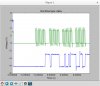
I made asimple XC8 program for PIC 18F25J11 ( https://ww1.microchip.com/downloads/en/DeviceDoc/39932D.pdf ) that reads ID from serial flash memory SST25VF040B ( **broken link removed** ). I have used spi library provided by XC8 for communication. Program appearantly successfully writes SPI command for reading device ID ( 9F H ) but when it fills buffer only with zero values although I can see valid MISO data on the scope.
Does anyone have any idea what could be missing here? Do I need to configure anything else about port RB1 to get it to work as an input?
Below I paste only a part of my code.
Thank you very much for any help!
Code:
void PIC_Init() {

    /***************************************************************************
     * SYSTEM CLOCK - 8 MHz x 4 PLL => 32 MHz
     **************************************************************************/

    INTSRC = 1; // Internal Oscillator Low-Frequency Source Select bit
    PLLEN = 1; //  Frequency Multiplier Enable bit
    IRCF0 = 1;
    IRCF1 = 1;
    IRCF2 = 1;

    /***************************************************************************
     * UART 2 PROPERTIES - BT32i
     **************************************************************************/

    // Configure UART 2 PPS pins
    iPPSInput(IN_FN_PPS_RX2DT2, IN_PIN_PPS_RP8); // Assign the Uart RX function to the correct pin
    iPPSOutput(OUT_PIN_PPS_RP7, OUT_FN_PPS_TX2CK2); // Assign the Uart Tx function to the correct pin

    // USART 2 - WT32i
    SPEN2 = 1; // RCSTA2<7>
    TRISB4 = 1; // the transmit bit - MUST BE SET TO 1 for asynchronus slave or 0 for asynchronus master
    TRISB5 = 1; // the receive bit - MUST BE SET TO 0
    LATB5 = 1;

    Open2USART(USART_TX_INT_OFF & USART_RX_INT_ON & USART_BRGH_HIGH & USART_CONT_RX & USART_EIGHT_BIT & USART_ASYNCH_MODE & USART_ADDEN_OFF, USART2_BAUDRATEREG);
    baud2USART(BAUD_IDLE_CLK_LOW & BAUD_WAKEUP_ON & BAUD_16_BIT_RATE & BAUD_AUTO_OFF);
    DTRXP2 = 0;

    // !! TODO !! CLEANUP

    WUE2 = 1; // Wake-up Enable bit
    CREN2 = 0;
    CREN2 = 1; //  Continuous Receive Enable bit
    TX2IE = 0; // TX USART Interrupt disabled
    SYNC2 = 0;

    /***************************************************************************
     * SPI FLASH - SST25VF040B
     **************************************************************************/

    PPSUnLock(); // Unlock the PPS functionality

    // Initialize remappable pin functions
    iPPSInput(IN_FN_PPS_SDI2, IN_PIN_PPS_RP4); // Assign MISO 2
    iPPSOutput(OUT_PIN_PPS_RP5, OUT_FN_PPS_SDO2); // Assign MOSI 2
    iPPSOutput(IN_FN_PPS_SCK2IN, IN_PIN_PPS_RP6); // Assign SCK 2 as input
    iPPSOutput(OUT_PIN_PPS_RP6, OUT_FN_PPS_SCK2); // Assign SCK 2 as output

    PPSLock(); // Lock the PPS functionality

    // FLASH CE
    TRISC2 = 0; // Output
    LATCbits.LATC2 = 1; // Idle high, active low

    // FLASH SCK
    TRISB3 = 0; // output
    LATBbits.LATB3 = 0; // Idle clock is low

    // FLASH MOSI
    TRISB2 = 0; // output

    // FLASH MISO
    TRISB1 = 1; // input

    OpenSPI2(SPI_FOSC_64, MODE_00, SMPMID);

}

void flashReadDeviceId(void) {
    FLASH_CE = FLASH_CE_ACTIVE;
    __delay_ms(5);
    WriteSPI2(0x9F);            // Command - read device ID
    getsSPI2(flashBuffer,3);    // Get x bytes
    __delay_ms(5);
    FLASH_CE = FLASH_CE_INACTIVE;
}

void main() {
    PIC_Init();
    volatile unsigned char flashBuffer[23] = "ABCDEFGHIJKLMNOPRSTUVZ\0";
    while (1) {
        flashReadDeviceId();
        puts2USART(flashBuffer);
        for (i = 0; i < 10; i++) {
            __delay_ms(10);
        }
    }
}