Electro Tech is an online community (with over 170,000 members) who enjoy talking about and building electronic circuits, projects and gadgets. To participate you need to register. Registration is free. Click here to register now.
Welcome to our site! Electro Tech is an online community (with over 170,000 members) who enjoy talking about and building electronic circuits, projects and gadgets. To participate you need to register. Registration is free. Click here to register now.
hi dale,
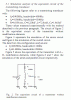
Look at this simulation using a typical equivalent circuit for a 40KHz transducer.
Its an unmodified model so its resonant at around ~39.5KHz, in a optimised circuit for 40KHz, additional Res/Caps would be added to fine tune to 40KHz.
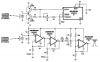
A curious connection between the first and second op-amp stages, I have not seen one like that before.
Is it a drawing error, or am I missing something?
I Agree, But this is Correct on both my drawing and the origional one.
Sorry I am not quite sure why.
Possibly some filtering action.
Unfortunately not much time now to play with it some more.
Connecting pin 5 to the Output at pin 1 (As would seem to be correct) Reduces Sensitivity.
The value of the 0.001uF capacitors in series with the 12k resistors reduces each gain to 0.71 times and reduces the gain of both to half the total gain of when the capacitors values are much more like 0.01uF.
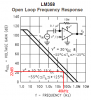
The max gain of an opamp in an LMLM324 or LM358 at 40kHz is only about 11 times when the supply voltage is from 10V to 15V.
hi chemelec,
The LM324 is totally unsuitable for this application.
At 40KHz the gain is too low.
I found a big difference in the 'echo' signal when using the drive transistor pair for the transmitter, when using a decent OPA receiver, ie: CA3240.
When using a LM324 the gain of the receiver is so awful that it masks any improvement shown by the transistor drive.
What reliable 'person' at the door echo range did you get it to work OK.?? Detection range.
I found an Applications Note in Maxim archives about this circuit. It was used to trigger a video message about a product when someone stops to look. It uses low power parts because it runs from a 9V battery all day.
It uses the transistors in the transmitter to prevent damage to the low power Cmos 555 when it tries to drive the resonant piezo transducer.
The receiver uses low power opamps that have normal high gain at 40kHz and it uses the filter made with R2 and C1 to prevent detection of someone walking past since it wants to detect someone pausing and showing some interest in the product.
hi chem.
I appreciate your circuit works OK for you, I would be interested to know the detection range.?
Some OP's are planning to use that type of circuit for an auto detect front door bell driver, by bouncing an echo of the person at the door, so any working info you have would be interesting.
I only built this on a breadboard and was getting a range of about 2 to 3 feet.
But I would recommend you build the Circuit in the PDF file, in post "32", by AudioGuru.
I don't have time now to check it out, but I am quite sure it would work with a better detection range.
If you can't get those MAX403 or the MAX406, I would try using a TL082 and a TL081.
(Or a Quad TL084) These have a 3 Mhz unity Gain.
(Definately an improvement over the LM324.)
The MAX43 opamps in the original Maxim circuit had negative feedback resistors providing voltage gain of 83 times for each one. The MAX403 opamps had an open-loop gain of 251 times at 40kHz so they were used, but are not available anymore.
A moron copied the circuit, added some errors and use the lousy old LM324 quad opamp instead that does not work at these frequencies. The TL07x, TL08x or TLE2141 will work fine.
hey guys,,
I had the task of simple iteration method,
how the application of simple iteration method in the microcontroller to regulate the flow of water.
and use the ultrasonic circuit too, What does this ultrasonic circuit have to do with microcontrollers and water flow control?
need sugestion please Stick to your existing thread.
Do not create multiple threads on the same subject.
Do not hijack other threads.
i have been trying with this circuit now for a few days and i couldnt get an output good enough to power a buzzer, i think it is because of the op amp used, also can i ask what are the capacitors used for in between the op amps and ground, im really struggling to understand the concept of this basic electronics never seems to amaze me, i dont really want to just build the circuits showing i want to know why and how you guys are really helping atm so im really greatfull
An opamp has a low output current. Your buzzer probably draws a higher current. The opamp can drive a transistor that can have a high output current.
The 0.001uF capacitors to ground in the Maxim circuit pass high frequencies so that the opamps have a gain of 1 at DC and have high gain at the ultrasonic frequency.
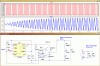
I Built up this circuit using a single TL074 and a 555.
I Still find No advantage in adding the Two transistors at the 555 output.
In the PDF file that was previously Posted, it says it Prevents "Undesirable Spikes".
Considering these Ultrasonic Transducers are High Impedance, so Not sure that is Possible.
And I don't see any on my Scope.
This site uses cookies to help personalise content, tailor your experience and to keep you logged in if you register.
By continuing to use this site, you are consenting to our use of cookies.