Continue to Site

Welcome to our site!

Electro Tech is an online community (with over 170,000 members) who enjoy talking about and building electronic circuits, projects and gadgets. To participate you need to register. Registration is free. Click here to register now.

  • Welcome to our site! Electro Tech is an online community (with over 170,000 members) who enjoy talking about and building electronic circuits, projects and gadgets. To participate you need to register. Registration is free. Click here to register now.

two capacitors in parallel with power supply

Status
Not open for further replies.

hanhan

Member
Hi,
I have read a lot about two capacitors in parallel with power supply but I still got stuck.
parallel-capacitors-in-power-supply-jpg.75326

Here is what I get:
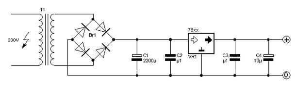
1. Big capacitors (electrolytic capacitor with large ESR and ESL) handles low frequency ripple and mains noise and major output load changes.
2. Small capacitors (ceramic capacitor with very small ESR and ESL) handle noise and fast transients.

My question:
1. At very high frequencies, the ceramic capacitor will be short, right? And why this shortage don't cause the power supply be damaged?
2. Why "electrolytic capacitor with large ESR and ESL" is excellent for "handling low frequency ripple and mains noise" and major output load changes and ceramic capacitor with very small ESR and ESL is excellent for "handling noise and fast transients"?
 

Attachments

  • parallel capacitors in power supply.JPG
    parallel capacitors in power supply.JPG
    21.1 KB · Views: 1,448
Hi,

The large capacitor handles the lower frequencies simply because it has a lot of capacitance and can hold the voltage over the time of the cycle or half cycle. The smaller cap cant hold the voltage long enough to filter properly.

The small cap can handle the higher frequency components because it has less inductance.

The higher the frequency the lower the amplitude of that component, so the diodes dont blow out.

The diodes could however blow out when the power supply is first turned on however if the input voltage is near the peak of the sine wave because the big cap acts like a pretty good short for a short time. So sometimes we have to insert a current limiting device in series with the rectifiers or just the input. Typically these will be thermistors that can handle higher currents and their resistance decreases as they heat up so after a short time their resistance goes down and the power supply acts normally.

We could look at the harmonics coming out of the rectifiers so you could get a better idea about the amplitude of each frequency component. As the frequency increases the amplitude goes down so there is less current at that frequency.
Also, the input transformer often has both series resistance and leakage inductance which also limits the current at many frequencies, and acts as a low pass filter too which reduces the higher harmonics too and also helps with the turn on surge current.
 
Thank you, MrAl.
To make sure I know what you mean, I will write my understanding below of yours.
The large capacitor handles the lower frequencies simply because it has a lot of capacitance and can hold the voltage over the time of the cycle or half cycle.
I think this is related to time constant τ= 1/RC. With large capacitance, τ=1/RC will be small.
Discharging equation of capacitor:
V = V(0)*e^(-1/RC)*t
where V(0) is the initial voltage of the capacitor.
τ=1/RC is small therefore the electrolytic capacitor will hold its voltage over a long time.
The smaller cap cant hold the voltage long enough to filter properly.
The same goes for ceramic capacitor, because its capacitance is small; it cannot hold the voltage long enough to filter properly.
However, I am confused about ESR of each capacitors.
Electrolytic capactitor has a large ESR while ESR of ceramic capacitor is very small.
And this seems not appropriate for charging of capacitor.
Charging equation of capacitor.
V = Vs*[1- e^(-t/RC)]
where Vs is the source voltage.
Electrolytic capacitors have a big resistance => constant time τ=1/RC is small and the capacitor will take a long time to be charged to source voltage, Vs.
This means that the capacitor voltage will cannot follow exactly source voltage in the charging process.
Is this a problem?
The small cap can handle the higher frequency components because it has less inductance.
At high frequency, Zc = 1/ωC and Zl= ωL will be very small and this capacitor can be considered as a short and the output voltage (the voltage across the capacitor) will be zero.
Is this the mechanism that ceramic capacitors cancel out high frequencies?
The higher the frequency the lower the amplitude of that component, so the diodes dont blow out.
I don't get that. Can you explain it more?
 
Simply at high frequency electrolytic capacitor has a much larger Zc than 100nF ceramic capacitor.

See this example

1a-png.75328


When you have a plot of a Zc Vs frequancy for 100uF electrolytic and 100nF ceramic cap.
Theory tells us that the Zc of a capacitor will decrease monotonically as frequency is increased. In actual practice the ESR causes the impedance plot to flatten out. As we continue up in frequency, the impedance will start to rise due to the ESL of the capacitor. This is why we often see larger value capacitors paralleled with smaller values. The smaller value capacitor will typically have lower ESL and continue to “look” like a capacitor higher in frequency.

https://forum.allaboutcircuits.com/showthread.php?p=296744#post296744
 

Attachments

  • 1a.PNG
    1a.PNG
    26.3 KB · Views: 1,079
Thanks Jony,
Theory tells us that the Zc of a capacitor will decrease monotonically as frequency is increased.
Yup, Zc = 1/ωC
In actual practice the ESR causes the impedance plot to flatten out. As we continue up in frequency, the impedance will start to rise due to the ESL of the capacitor. This is why we often see larger value capacitors paralleled with smaller values. The smaller value capacitor will typically have lower ESL and continue to “look” like a capacitor higher in frequency.
For example, the capacitor in the circuit above is ideal, there is no ESR and ESL at all. Thus, we only need one capacitor with large capacitance to cancel out high frequencies, right?
At low frequencies, electrolytic capacitor will act as a capacitor and at high frequencies ceramic capacitor will act as a capacitor. Therefore, if we use both capacitor to act as one capacitor in all frequencies?

And I am bit confused, for example, at low frequencies electrolytic capacitor will act as a capacitor but at the same time how ceramic capacitor affect the operation of the circuit?
 
For example, the capacitor in the circuit above is ideal, there is no ESR and ESL at all. Thus, we only need one capacitor with large capacitance to cancel out high frequencies, right?
Yep, that's right

At low frequencies, electrolytic capacitor will act as a capacitor and at high frequencies ceramic capacitor will act as a capacitor. Therefore, if we use both capacitor to act as one capacitor in all frequencies?
I don't understand the question.
And I am bit confused, for example, at low frequencies electrolytic capacitor will act as a capacitor but at the same time how ceramic capacitor affect the operation of the circuit?
At low frequencies electrolytic capacitor will act as charge reservoirs to transient currents (AC current). A ceramic at low frequencies don't "hold" enough amount of energy (E = 0.5C*V^2). So we can ignore it. But we have 100uF + 100nF effective capacitance at low frequancy.
 
I don't understand the question.
Okay, no problem! I meant that two capacitors are used to compesate each other and the two capacitors will act as an ideal capacitor.
At low frequencies electrolytic capacitor will act as charge reservoirs to transient currents (AC current). A ceramic at low frequencies don't "hold" enough amount of energy (E = 0.5C*V^2). So we can ignore it. But we have 100uF + 100nF effective capacitance at low frequancy.
100uF + 100nF ≈ 100uF and that don't affect much to the operation of the circuit.
Here is a stupid question but I am not sure.
When we say about filter, do you mean filter voltage or current?
I think it should be current because the voltage at output of bridge rectifier and across two capacitors are always equal!
If we draw the load, then the current through load will be the current remained after filter, right?
 
Normally when we talk about filter we think in terms of a voltage filter. But in this case we can think in terms of a current also. Because capacitor will high frequency short component to ground.
Kept in mind that current in the capacitor is proportional the rate of voltage change across it (proportional to how quickly the voltage across capacitor is changing). The faster the voltage change (frequency of a AC signal is high) the large the current flow through capacitor.
I = C * dV/dt
This means that to sustain current through a capacitor the applied voltage must change. The more rapidly voltage changes the larger the current.
 
Status
Not open for further replies.

Latest threads

Back
Top