Continue to Site

Welcome to our site!

Electro Tech is an online community (with over 170,000 members) who enjoy talking about and building electronic circuits, projects and gadgets. To participate you need to register. Registration is free. Click here to register now.

  • Welcome to our site! Electro Tech is an online community (with over 170,000 members) who enjoy talking about and building electronic circuits, projects and gadgets. To participate you need to register. Registration is free. Click here to register now.

Triac Troubleshoot

Status
Not open for further replies.

ibwev

Member
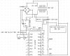
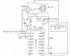
I am attempting to control a 24 VAC contactor via PIC16F690 using a 3 quadrant triac (https://www.electro-tech-online.com/custompdfs/2012/12/BTA2008W-600D-1.pdf). The contactor works beautifully when I connect it to the triac via a 5 volt supply through a 220 ohm resistor; however, it does not work so well going through the pic. To troubleshoot the problem, I assembled the attached circuit. When SW1 is closed and SW2 is opened, the contactor closes AND the led connected to RA5 illuminates. What might cause the LED to activate?
 

Attachments

  • ContactorTroubleshoot.png
    ContactorTroubleshoot.png
    15.3 KB · Views: 198
You have your transformer drawn wrong. If it is wired as drawn you could put mains voltage into the low voltage stuff.
You need a filter cap after the full wave bridge to Make DC.
 
You need a filter cap after the full wave bridge to Make DC.

I added a 10 μF ceramic capacitor rated at 50 V at the in and out port of the voltage regulator as illustrated.

ContactorTroubleshoot2.png

The datasheet for OKI-78SR-5/1.5-W36-C (https://www.electro-tech-online.com/custompdfs/2012/12/oki-78sr.pdf on page 11) says:

Recommended Input Filtering
The user must assure that the input source has low AC impedance to provide
dynamic stability and that the input supply has little or no inductive content,
including long distributed wiring to a remote power supply. The converter will
operate with no additional external capacitance if these conditions are met.
For best performance, we recommend installing a low-ESR capacitor
immediately adjacent to the converter’s input terminals. The capacitor should
be a ceramic type such as the Murata GRM32 series or a polymer type. Initial
suggested capacitor values are 10 to 22 μF, rated at twice the expected maximum
input voltage. Make sure that the input terminals do not go below the
undervoltage shutdown voltage at all times. More input bulk capacitance may
be added in parallel (either electrolytic or tantalum) if needed.


With the addition of the 2 capacitors (as illustrated), the pic still lit the light. Do I need to adjust the capacitor size or add either electrolytic or tantalum capacitors? If so, what size?
 
You are going to need alot more than 10uf to filter out the ripple from the full wave bridge rectifier. You need to look at power supply theory not the regulater data sheet.
the pic still lit the light
You may have to set RA5 to the right state the LED will light if RA5 is high.

What is SW2 and AC voltage to RB4 for??
 
Last edited:
You need to look at power supply theory ....

Please suggest a resource that a beginner may study to learn how to appropriately supply power from a 24 VAC transformer to a microcontroller.


What is SW2 and AC voltage to RB4 for??

This is a section of a circuit I am trying to develop. The pic will sense when a 24 VAC signal goes high then do a series of test before relaying the signal to the contactor. SW2 is temporary to practice sending a signal through RB4. Once I correct the power supply, RB5 will relay the signal to the triac which will turn on the contactor.
 
if the LED is wired the way it is drawn, it is reverse polarity. This means that it will not illuminate unless RA5 goes BELOW ground.

There is no diode on the 10k into RB4, so with SW 2 open the input will be clamped at .7 below ground and .7 volt above 5V, as there is a return path through the ground of the micro and the (-) of the bridge. This may be where the current is coming from to light the LED. Also, SW2 through the 500K is at the opposite polarity as the 10K resistor. It looks like you're trying to divide down the 24VAC through the 500K and 10K resistors, but what is happening is there is a lower impedance path back through the bridge through the ground connection. You don't need the return path to 24VAC through the 10k, it should be tied to ground. Also, to obtain 5V when SW2 is closed, the circuit should be 24VAC to a diode to a 56K resistor to SW2 to a 10K resistor and RB4 and then the other side of the 10k tied to ground.

modified circui4t.JPG current path 1.JPG
 
Last edited:
You are going to need alot more than 10uf to filter out the ripple from the full wave bridge rectifier.

10uF will remove all of the ripple from the bridge, as long as you don't pull any current out:)

dI/dt = c * dv/dt... which means the change in current per unit time = the capacitance times the change in voltage per unit time. In other words, the more current you want to pull out, the higher the capacitance has to be for a fixed dv/dt (change in voltage or "ripple voltage"). Or, if you have a fixed capacitance, the larger the current you pull out of it, the larger the ripple voltage.

Or, like 4pyros said, "You are going to need alot more than 10uf". 10uF on the output of the regulator is good to filter transients on the regulator output, but you'll need a much larger bulky to filter the ripple of the bridge. Probably somewhere above 4700uF, but depends on what ripple you allow yourself and the current of your system. Also, you don't need to filter it all out, but you have to keep the valley above the dropout voltage of the regulator. There is some line transient that shows up on the output, but it's not 1 to 1 (that will be on the regulator data sheet).
 
Please forgive me for asking a really dumb question but I do not want to blow up this capacitor. I am afraid I would have fireworks comparable to 4pyros picture if I reversed polarity.

1) Did I appropriately mark the + and - terminals in the diagram?

CapacitorPolarity.png

2) Is it safe to add another 1000 μF electrolytic capacitor in parallel with the capacitor listed above?

3) Can the power supply damage a circuit if it has too much capacitance?
 
capacitors in parallel add up like resistors in series. By the same token, capacitors in series add like resistors in parallel. You can put as many caps in parallel as you want, the only limit is make sure the voltage of the lowest one is above the expected circuit voltage. A lot of switching power supplies use up to 8 or 10 capacitors in parallel instead of one big one. This is to lessen the esr (equivilent series resistance). Sometimes you are limited on the vertical height of your board/system, so you use more shorter caps.
 
I added the above pictured capacitor (frame 9) to the circuit illustrated below (I did not include the resistor or voltage regulator when I assembled it). I noticed the voltage increased (no load) from 27.7 volts without capacitor to 38 volts with capacitor. The datasheet (https://www.electro-tech-online.com/custompdfs/2012/12/oki-78sr-1.pdf) of the voltage regulator states a maximum voltage of 36 V.

powerplane.png

1) Since the capacitor increased the voltage, should I add a resistor to bring the voltage to a safe range for the voltage regulator?

2) If yes, should the resistor size be: R=V/I where V is the desired voltage difference & W=VA
= V/(W/V) A=W/V
=Vsquared/W
=8squared/1/4 watt
=256 Ω resistor
 
most transformer secondaries are rated in V at a given current draw. Therefore, the V will be higher under no loads. Adding a capacitor after a bridge gives you 1.414 the acV rating on the DC. This is due to the fact that 24VAC has a peak value of 39V (the 24 is the rms value).

A better way to do it would be to half wave it, or center tap and do full wave. That would lower the voltage without throwing power away on a resistor. If your regulator is only 5V, then you can stand a whole lot lower voltage coming off the rectifier circuit.

by your calculations, 256 ohm would be the minimum resistor you should use to obtain 1/4W. Running this kind of power through a 1/4W resistor is ok at 25°C, but you need to derate that for higher ambient temperatures. The rule of thumb is to derate by 2, or use a 1/2W resistor to dissipate 1/4W. A more common way to do this is to put a resistor in series with the input to the regulator. Divide the voltage you want to drop by the current drawn by the regutor to find the resistor value. The resistor power rating will be v * v / r.
 
It might be best to change the 7805 regulator to a LM317 then you would be safe even at high line. Or if your only load is the PIC and LED a little zener shunt regulator would also work. A little more wasted power but simple.
 
Also, that 35V capacitor should be a 50V. Even if you only expect 30V, the more cushion you have at the top (the lower the % of voltage to capacitor working voltage), the longer a capacitor lasts.
 
The simplest way would be to use half wave rectification. IE one diode.
This will lower the voltage but you will need more capacitance to cover for the missing have wave.
You could use two caps with a coil between them. IE a pie filter.
With that your combined capacitance would be less than a single cap.
 
I too am enjoying some pie right now; however, it is easier on me to follow the recipe on the pie I am eating than it is for me to follow the recipe on the pi filter I am attempting to design. I found a youtube video with a possible starting point for the capacitor and choke size.
**broken link removed**
The circuit the power supply would need to serve has a maximum load of 369 mA.
1) With a 5 volt supply, am I interpreting Ohm's law correctly to say that the load on my circuit is 14 Ω (5V/.369A)?

2) If 14 Ω is correct, that appears to be a substantial difference from the 167 Ω load on the video. Do I need an oscilloscope to determine the capacitor and choke size for my circuit?
 
Status
Not open for further replies.

Latest threads

New Articles From Microcontroller Tips

Back
Top