Electro Tech is an online community (with over 170,000 members) who enjoy talking about and building electronic circuits, projects and gadgets. To participate you need to register. Registration is free. Click here to register now.
Welcome to our site! Electro Tech is an online community (with over 170,000 members) who enjoy talking about and building electronic circuits, projects and gadgets. To participate you need to register. Registration is free. Click here to register now.
wow...i never thought about it. but just writing the program for the builtin hardware is already complicated. but i'll give it a try. thx for the suggestion!
wow...i never thought about it. but just writing the program for the builtin hardware is already complicated. but i'll give it a try. thx for the suggestion!
Oh, i seem to have tforgotten to mention one more thing. If i continue end up building another hbridge for my 2nd motor, it would COST me alot of money.
The problem is in my country here(malaysia), mosfets are hard to get in regular electronics shop and have to be ordered thorugh certain companies. The international rectifier mosfets they are selling cost 10 bucks each. I seriously find it ridiculous to spend 80 bucks on 8 mosfets. So, instead of using mosfets for as my transistors, i plan to use darlington pair(cost around 3 bucks or less each)
After reading through the datasheets, they dont mention anything about the switching frequency.
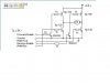
Does anyone have any experience dealing with the darlington pair? are they capable of 1000 hz pwm switching? but there are websites that use them. im really unsure whether to use them. The diagram below is an example of it. dont remember where i got it though
i have been seeing the 16F684 in the featured products list at the microchip website for quite some time. its really an impressive device. 8 channels of 10-bit A/D, two comparators, 4-ch PWM 10-bit, internal oscillator, 12 I/O pins in a 14-pin package.
i dont know about the switching characteristics of darlingtons as compared to MOSFETs but i do know that darlingtons are used in H-Bridge circuits with PWM. go to the page **broken link removed** for more details. the circuit uses the TIP120 and TIP125 darlington transistors which are commonly found everywhere.
one thing that i would like to point out is that Nigel's PWM tutorial uses two PWM channels. you could also use two PWM channels for two motors. one motor will drive the two wheels on the left and the other will drive the two wheels on the right by two drive belts. that way you wont need to have 4 motors. but that would be possible provided that the motors are capable of dragging the load. now thats up to you to experiment with
It seems that the 16F684 is made specifically for A/D conversions and PWM functions seeing the number of I/o it has. But unfortunately, i just bought a 16F876 seeing it has most of the features i require. 8)
I dont really get Nigel tutorial on the PWM though. How isit possible that 2 PWM channels are capable to control forward and reverse of 2 motor. I better ask him this in his support forum
I'll answer it here! - there's one PWM channel per motor, one for right, and one for left. The PWM only controls the speed of the motor, the direction is controlled by either one or two logic ouputs - depending on your specific H-Bridge hardware.
In my tutorial example I give 128 different speeds (which seems more than enough), if the highest bit is '1' (that is, for numbers from 128-255) the H-Bridge is set to reverse. So you have 128 forward speeds (0-127) and 128 reverse speeds (128-255).
This seemed a simple way to do it, and only uses a single byte for both speed and direction control.
Nigel that was clear from the PWM page but what is not clear is that are you driving two wheels with one motor or are you driving one wheel with one motor.
in a car you have four wheels right! two in the front and two in the rear. and your code will drive two motors. which configuration will be best to drive a car. i mean where will you connect the motors. will the motors be connected to the front wheels or the rear wheels.
or how about one motor driving both the wheels on the left and one motor driving both the wheels on the right.
Looking at this diagram. 1 input is required for forward and 1 for reverse.
This means that 2 PWM channels are required.
As Nigel mentioned earlier, that the direction is controlled by the inputs not the PWM. But looking at this, it seems the only way to control the speed AND direction is by PWM.
I've seen hbridge driver ICs offering an ENABLE option to input a PWM signal so tha 1 motor i controlled by 1 channel. But i rather build my own circuit.
I cant seem to visualise how does Nigel h bridge cct looks like
This site uses cookies to help personalise content, tailor your experience and to keep you logged in if you register.
By continuing to use this site, you are consenting to our use of cookies.