Keith42
New Member
Hi, i am trying to build a power supply for a GE ne-42 neon lamp. All it really needs to operate is about 60v, however, only the negative electrode of the lamp glows, so i am trying to generate some AC power from AA batteries so that both electrodes will glow.
I tried to do this using a 555-timer circuit, two transistors, and a center tapped transformer. The timer turns on/off the transistors at around 60hz, the transistors being opposites (NPN vs PNP) so that when one is on, the other is off. The center line from the transformer is attached to positive power terminal, and then each of the two end lines of the transformer run to one of the transistors.
My power source is 8 AA batteries, or about 12v at maximum.
My problem is that the NPN transistor never seems to allow power to flow. The PNP one works just fine, however with only one of them ever passing power, my transformer generates pulsed DC power instead of AC. As such, only one terminal of the lamp is lighting. I have tried the PNP transistor in both its spot and the spot where the NPN normally resides, it works in both, so that is not the problem.
On both transistors, the base is connected to the output of the 555, the collector to one of the end wires of the transformer, and the emitter to ground.
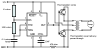
Using the diagram Here i have:
Resistor one: 1 kOhm
Resistor two: 100 kOhm
Capacitor: 0.1 microFarad
The two transistors i got from radio shack are This and This.
As best i can tell, the timer circuit works correctly. If i double resister two to take it down to 30 hz, the lamp visually flickers.
This confounded NPN transistor has me hung up though. Ive already replaced it once, no change. I read that you need a minimum 0.7 volt differential between base and emitter for the transistor to close, if i hold multimeter to those pins it reads about 0.55 volts. I don't know if that is really worth anything since the base pin's power is being switched on and off at 60ish hz. If i connect the NPN's base directly to +v it does close and let power flow.
Now, i really have minimal idea what i am doing here. Ive already exploded one battery when i didn't put any resistor in line with the transformer's ground (100 ohm there now). I hadn't the foggiest idea what a transistor was until i wiki'd it, and my understanding is still basically "whatever power you put to base allows power to flow from collector to emitter proportionally". I only partially understand how the capacitor makes the 555 timer set up work, but hey, it IS working. I basically found these neon lamps on some steampunk instructables, thought they were cool, ordered a few, and then got to thinking how the heck to get both terminals to glow.
Thanks in advance for any help, i hope this was sufficiently descriptive, and i pray that those who actually know what they are doing with transistors will be able to bonk me on the head and say "well there's your problem!" and illuminate what silly thing i have done wrong.
I tried to do this using a 555-timer circuit, two transistors, and a center tapped transformer. The timer turns on/off the transistors at around 60hz, the transistors being opposites (NPN vs PNP) so that when one is on, the other is off. The center line from the transformer is attached to positive power terminal, and then each of the two end lines of the transformer run to one of the transistors.
My power source is 8 AA batteries, or about 12v at maximum.
My problem is that the NPN transistor never seems to allow power to flow. The PNP one works just fine, however with only one of them ever passing power, my transformer generates pulsed DC power instead of AC. As such, only one terminal of the lamp is lighting. I have tried the PNP transistor in both its spot and the spot where the NPN normally resides, it works in both, so that is not the problem.
On both transistors, the base is connected to the output of the 555, the collector to one of the end wires of the transformer, and the emitter to ground.
Using the diagram Here i have:
Resistor one: 1 kOhm
Resistor two: 100 kOhm
Capacitor: 0.1 microFarad
The two transistors i got from radio shack are This and This.
As best i can tell, the timer circuit works correctly. If i double resister two to take it down to 30 hz, the lamp visually flickers.
This confounded NPN transistor has me hung up though. Ive already replaced it once, no change. I read that you need a minimum 0.7 volt differential between base and emitter for the transistor to close, if i hold multimeter to those pins it reads about 0.55 volts. I don't know if that is really worth anything since the base pin's power is being switched on and off at 60ish hz. If i connect the NPN's base directly to +v it does close and let power flow.
Now, i really have minimal idea what i am doing here. Ive already exploded one battery when i didn't put any resistor in line with the transformer's ground (100 ohm there now). I hadn't the foggiest idea what a transistor was until i wiki'd it, and my understanding is still basically "whatever power you put to base allows power to flow from collector to emitter proportionally". I only partially understand how the capacitor makes the 555 timer set up work, but hey, it IS working. I basically found these neon lamps on some steampunk instructables, thought they were cool, ordered a few, and then got to thinking how the heck to get both terminals to glow.
Thanks in advance for any help, i hope this was sufficiently descriptive, and i pray that those who actually know what they are doing with transistors will be able to bonk me on the head and say "well there's your problem!" and illuminate what silly thing i have done wrong.