Pro_Grammar
Member
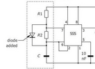
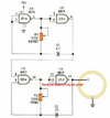
I'm trying make a non microcontroller circuit that gives about 5 quick beeps then roughly 1 second off, repeat. I'm running on 2 AAA batteries. I already have a bunch of cmos 555 on hand so was trying to make that work. I'm using a 3V active buzzer which is quite loud. I tried a few astable variations, the attached circuit with R1=1K (in series with variable resistor), R2=100K, C=10uF gave me the desired timing sequence but doesn't beep, just a steady on, 1 second off, repeat. What changes can I make to get the desired timing but with beeps.
Thanks,
Rich.
Thanks,
Rich.