Continue to Site

Welcome to our site!

Electro Tech is an online community (with over 170,000 members) who enjoy talking about and building electronic circuits, projects and gadgets. To participate you need to register. Registration is free. Click here to register now.

  • Welcome to our site! Electro Tech is an online community (with over 170,000 members) who enjoy talking about and building electronic circuits, projects and gadgets. To participate you need to register. Registration is free. Click here to register now.

Transistor heat levels

Status
Not open for further replies.

AxelD

New Member
Hi,

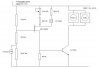
I hope someone will be able to assist me. Im building a simple fan controller with a transistor (TIP31) and i have some concerns on the heat levels of the transistor.

According to my calculations, there is at most 1W of power dissapated from the transistor.

Is it normal for the transistor to get this hot at 1W? (i cant really touch the metal portion of the TIP31 (TO-220 package)).

Do i need a to install a heatsink or is it fine that the transistor runs this hot?

Thanks
 
If its a Bi-polar transistor, and you don't have suitable current limiting/feedback, it can suffer from thermal runaway. A heatsink is always a good idea, especially if it is enclosed. Have you measured the actual current it is drawing?
 
Do you have resistors or diodes in this circuit?
 
A TIP31 can safely run too hot to touch (125c), but it's much more reliable when you keep it cooler.

Just a square inch of aluminum bolted to the back can work miracles.
 
At its lowest setting, the voltage across the transistor is about 12v with a current of about 60ma. Ive monitored the circuit for about an hour and the current moves up by about 2-3 ma as the transitor heats up.

The feedback makes sense but i control the current through the transistor with a POT. If i add feedback then wont any changes i make (by changing the pot and therefore the resistance) be cancelled out?

There are resistors but no diodes. A pot controls current to the transistor and i have the fan connected to the emmiter of the transistor.

Am i reading this correctly then - i dont need a heatsink but it is recommended given the circuit will be enclosed?

Thanks

hi Axel,
When you say the circuit will be enclosed, can you explain.:)
 
Axel - regarding the enclosure of the circuit, consider this: if you have a transistor that gets warm it will loose heat to the surrounding air at a rate that is dependent on the difference between the transistor (and heat sink if it has one) and the surrounding air - and also depedent on the resistance to the flow of heat (could be called thermal insulation) between the transistor/heat sink and the surrounding air.

If you enclose your transistor/heat sink it will get warmer as the enclosure adds some resistance to the flow of heat - another way to put it is that it serves as thermal insulation. As you insulate the enclosure the flow of heat will be reduced, the transistor/heat sink temperature will continue to rise - taken to the extreme the temperature inside an infinitely insulated enclosure would rise until the transistor fails.

I offer this explanation as a way of emphasizing that the details of the enclosure do matter. I think it is safe to say that heat sinks and enclosures can be carefully designed - with detailed design of every aspect but often the end result is a combination of design estimates, experience and some guesswork combined with testing - basically "cut-and-try" approach.
 
This sounds a bit weird :) but the fan controller is actually not for a PC but for a cupboard in my lounge area. The circuit will be housed in a 7x7 cm plastic box which will be mounted within the cupboard.
 
Thanks to everyone for the replies.

stevez - im a bit more concerned now given the small size of the plastic box i intend to use and the lack of ventilation. I may need to scrap the box idea ...
 
As an aside, does transistors generally get this hot in certain applications (eg. fan controllers) or does it reflect bad circuit design - i read somewhere on a forum or site that if the transistors are heating up there is a problem with the design.

True or False?
 
Thanks to everyone for the replies.

stevez - im a bit more concerned now given the small size of the plastic box i intend to use and the lack of ventilation. I may need to scrap the box idea ...

Why not use a aluminium diecast box and use that as the heatsink.?
 
Axel - as a general rule, higher temperatures mean reduced life, reduced reliability however many components are designed to provide long life and high reliability at elevated temperatures. Good design, in my opinion, strikes a balance between use of resources (money, time, space, etc) and meeting your needs - reliability being one of those needs. If a transistor can run warm or hot and still get the job done in a sufficiently reliable way then consuming more resources might not be judged as good design by some.

A possible solution could be to provide some means to let air circulate thru the enclosure. Sometimes one side or all of the enclosure can be metal - with the transistor mounted to the metal as a heat sink - the transistor being mounted so it is electrically but not thermally isoloated. Care must be taken at higher voltage levels.

Nothing wrong with your application - most of us here adapt proven designs to suit our needs. Lots of fun to be had and much learning results.
 
Last edited:
A TIP31 can safely run too hot to touch (125c), but it's much more reliable when you keep it cooler.

Just a square inch of aluminum bolted to the back can work miracles.

Don't forget that, that's the rating for the junction temperature, not case temperature.
 
It is not that I doubt your circuit, but could you post your circuit AxelD. I think it would help everyone here out a lot more if you did. Is your V(ebo) greater than 5vdc? If so transistor is no good for that voltage.
 
Why not look at the datasheet for the TIP31 transistor?
It shows a max allowed dissipation of 2.0W when the surrounding air is 25 degrees C.
Then its internal chip temperature is at the max allowed temperature of 150 degrees C and it might fail soon.
 
I will post the circuit later - need to draw it up in word or some other program :).

B reagle - im not too sure what you refer to by V(ebo). According to my calculations, the base voltage of the transistor is max 2v (base to ground). The voltage i measure from the collector to emitter varies from 0.5v to 12v.

audioguru - I had a look at the datasheet but i wasnt sure what that figure represented. There was also a 40w figure if i recall.
 
Ok, so as far as the transistor heat dissapation issue goes:

1. In some applications it is normal for the transistor to heat up.

2. TIP31 can dissapate 2W of power under normal conditions. So the transistor should handle 1W no problem without a heatsink.

3. However given the small enclosure, a heatsink wouldnt be a bad idea as the ambient temperature is probably going to be higher than 25 degrees C.

4. Best way is to attach a piece of aluminium to one side of the box and use it as a heat sink.

If i have misunderstood anything let me know.
 
Heres more or less my full circuit. Im a newbie so im sure there are a quite a few mistakes. Go easy on me ...

Now that the transistor issue is sorted, the next issue i have is that im running the fans off a switchable wall transformer (3v,4,5v, ... , 12v) thats not regulated so the voltage varies between 12 and 15 volts. What is the best way to get better regulation given the 12-15 volt swing? 7812 or 12v zener?
 

Attachments

  • circuit1.JPG
    circuit1.JPG
    26.1 KB · Views: 177
What is M1? it looks like a Mosfet. What does it do?

When you turn on the power to the circuit with the speed set low then the fans might not start running because the starting current is more than the running current.

The circuit does not need a voltage regulator. When the speed is turned down and the voltage increases then it doesn't matter.
 
B reagle - im not too sure what you refer to by V(ebo). According to my calculations, the base voltage of the transistor is max 2v (base to ground). The voltage i measure from the collector to emitter varies from 0.5v to 12v.

https://www.fairchildsemi.com/ds/TI/TIP31.pdf is the datashhet I looked at, and in the first chart is where V(ebo) is. I got 5.36V max by using I(total)=V(max)/R(total)
Which I used 15V and 2850ohms=5.35mA
V(r)=5.35mA* R
Which I used 1k for R
And I got 5.36V on the base to common.
R(total)=2850ohm to 3913ohm (on the base)
I am a little rusty with this math. I hope it is right!!


Again I am not sure if this is right.
 
Last edited:
Status
Not open for further replies.

Latest threads

New Articles From Microcontroller Tips

Back
Top