Hello, I am trying to make the Darlington pair circuit found on http://www.kpsec.freeuk.com/trancirc.htm (The one under the dotted green box)
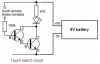
I think the problem is simply that I am reading the schematic wrong. I have the +9v connected to the 470 and 100k resistors. Then the 100k connected to B. Then E to B. Then I cannot figure out what to do. I dont understand why the LED goes from +9v through the resistor and then after the +9v comes through the two transistors it is connected to the cathode because the voltage is still positive, right? Then what is the 0v for at the bottom? To me it looks like both positive and negative flow through the transistors. Could you clear this up for me? Thanks a lot!
I think the problem is simply that I am reading the schematic wrong. I have the +9v connected to the 470 and 100k resistors. Then the 100k connected to B. Then E to B. Then I cannot figure out what to do. I dont understand why the LED goes from +9v through the resistor and then after the +9v comes through the two transistors it is connected to the cathode because the voltage is still positive, right? Then what is the 0v for at the bottom? To me it looks like both positive and negative flow through the transistors. Could you clear this up for me? Thanks a lot!