Continue to Site

Welcome to our site!

Electro Tech is an online community (with over 170,000 members) who enjoy talking about and building electronic circuits, projects and gadgets. To participate you need to register. Registration is free. Click here to register now.

  • Welcome to our site! Electro Tech is an online community (with over 170,000 members) who enjoy talking about and building electronic circuits, projects and gadgets. To participate you need to register. Registration is free. Click here to register now.

Transistor based AC amplifier - how to build with limited details.

Status
Not open for further replies.

Ara Ghazaryan

New Member
I am new to electronics. And somehow I got the following task:

goal: Amplification of signal from function generator (FG) using home-built circuit based on transistors.
details:
FG output -6 - +6V.
needed output after amplification -24 - +24V.

details I have -
FG
transistors TO92 2N5551 936 (others can be ordered)
resistors - any
DC Power supply - 24 V (can be regulated).
Frequency this thing will operate in - 1-15 Hz
diodes and capacitors can be ordered if needed.

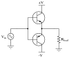
I already built a simple amplification circuit for DC output (shown attached), but now it turns out I need alternating current in the output.
415cb717-0a6d-42fc-9df8-9fe8545f1398.png


I researched and stumbled upon Push-and-pull amplifier circuits. But if I understand correctly -- these will output -12,5 V to + 12,5 V range, right?
Can you suggest which directions I should look into?


Thanks
 
What are the very important specifications for voltage and current of the light bulb?
Did you look at the datasheet of the transistor to see if it can drive the voltage and current of the light bulb?
Why are you shorting the positive-going output of the function generator with the base-emitter diode of the transistor? When the AC from the generator swings negative then it might damage the base-emitter diode that has an absolute maximum allowed voltage of 6V.
Did you know that an incandescent light bulb draws 10 times its normal current when it is cold and then the transistor might burn out?
AC or DC on a light bulb makes no difference.
Many push-pull audio amplifiers operate from a single supply voltage and produce an AC output to a speaker because they use a capacitor in series with the speaker that blocks DC but passes AC.

Thanks for a prompt answer!

Now I will try to answer most of your questions - the so depicted bulb is actually a magnet coil. No specs for it exist other then it operates under 24 V. The idea is to use AC to double the effect of it.
FG output was never negative - it is programmed to rectangular pulses of 4-5 V. (though for new circuit I can of course make it output in -5 to +5 range)
as far as i could understand the datasheet of transistor it can operate with V emittor base = 6 and V colector base = 160. So I guess I am safe on this side.
The resistor stands there based on some circuits I saw on internet and almost intuitively - without it transistor heats up, with it it does not.
I cannot block DC as what I want is ramp steps of -24V to 24 V with ~4 Hz.

Hope I covered some of the questions. For the remaining please re-ask more specifically with this info take into account.
Thanks again!
regards
 
Last edited:
Now you say the light bulb is actually a magnet coil?? Then why did you show a light bulb?
You cannot design a circuit that drives a magnet coil without knowing how much current the coil will draw from 24V. It might be 10A or more. The transistor has an absolute maximum allowed current of only 0.6A.
A coil has inductance that produces a very high voltage spike when the transistor turns off. Therefore the coil needs a parallel diode to arrest the voltage spike.
The datasheet of the transistor shows that its forward base-emitter voltage is about +0.9V when its current is 200mA but you are blasting +4Vto +5V at it which can easily destroy it. You need a series resistor to limit the current.
The graph in the datasheet of the high voltage 2N5551 transistor shows that is current gain drops above only 10mA and is zero at a few hundred mA.
Your circuit does not have -24V, it has only 0V and +24V. The voltage steps will be from 0V to near 24V, but your circuit has nothing to sense then control the output voltage steps so its output might be almost 24V or nothing with no steps, or the voltage will vary all over the place as the transistor warms up.
 
The idea is to use AC to double the effect of it.
:confused: Ignoring inductive effects, the same peak current would flow (hence same magnet strength) whether the coil gets +24V or -24V. Only the polarity changes.
 
sorry for misleading - the bulb depicted on corcuit stands for load. any. i had no idea bulding amplifier for magnet would be different.
The circuit I attached is for refference only - it was used for "positive" amplification (worked alright, by the way) but now of course i have to change it. As far as i understood - to build pushh-and-pull AB type amplifier i will need another transistor,at least 2 more diods and resistors.
Knowing the parameters of magnet would help ov course, but unfortunatelly I dont know the specs -nothing is written on it. one of the coils that is used to pull lock hinge or somethin like that.
FG output was set to 2V in my case. I used series resistor, i draw it paralel by mistake. I can also check the resistance of it.

as for the overall question - if I build a push and pull amplifier based on two transistors (two roots divided by diods, for positive and negative driving voltage) will I end up with -12,5 and +12,5 V only?
thanks
 
exa
:confused: Ignoring inductive effects, the same peak current would flow (hence same magnet strength) whether the coil gets +24V or -24V. Only the polarity changes.
exactly. and given that it will be used on a magnet it will not only pull and release(as previously) but also repell, right?
 
One other point. You can't build an amplifier to give an output +/- 24 volts with only a single 24 volt supply. (Unless you use a transformer on the output but I would not advise that approach.) Your first step will be to find a way to generate about +/- 28 volts from the 24 volts you have available.

Les.
thanks. so i doubted. though I wasnt sure - thought using some sort of diod bridge i can direct current (hence polarity - i know, now when i write it sounds wrong).
so to summ up - disregarding a few volts of difference (24 vs. 28) I still need two separate power supplies? thanks
 
Knowing the parameters of magnet would help of course, but unfortunatelly I dont know the specs -nothing is written on it.
It is extremely easy to measure the resistance of the coil with a multimeter then use Ohm's Law to calculate its current when it has 24V. Current = 24V/Resistance. Its reactance (AC resistance) is higher at higher frequencies.

You do not need two power supplies. You can get +24V and -24V from a push-pull amplifier powered from about 52V and a series output coupling capacitor. Or you can use a bridged amplifier that has two push-pull amplifiers, each powered from the same 14V, each amplifier driving opposite ends of the coil with opposite phases.
 
so to sum up and clarify:
On the controlling input I have a function generator with maximum voltage +- 5V.
Also I have (found) 30 V power supply.

I found this circuit:
class-ab-push-pull-amplifier.png


So this circuit will provide +- 15 V on the load depending on the input signal, right?

Also I do entirely understand the purpose of C1 and C2 and as a result - have no idea what the capacities of those shall be.

Thanks for any comments

P.S. thanks for advice, Audioguru, " Or you can use a bridged amplifier that has two push-pull amplifiers, each powered from the same 14V, each amplifier driving opposite ends of the coil with opposite phases." - how this can be done?
Thanks!
 
You still do not have an "amplifier" because it does not amplify the signal voltage level. If its input capacitors are calculated to pass thye lowest frequency you want then its output signal level will be slightly less than its input signal level because the transistors are simple "emitter followers" (look it up in Google). Also the output will have a DC voltage that is not suitable for a speaker.
If the input is +- 5V then the output will be +- 4.9V.

The input capacitors pass the AC signal but block the DC "pre bias" from being shorted to ground by the input signal generator.
I have never seen an audio amplifier that uses these capacitors. Usually an audio amplifier has its stages DC-coupled.

Here is an audio amplifier that is the most simple:
 

Attachments

  • simple amplifier 3.GIF
    simple amplifier 3.GIF
    9.9 KB · Views: 227
Sorry for not being precise from the very beginning.
I would have outlined what I need this circuit for from the very beginning (noob exposed :( ).

The circuit shall not be used for sound It will be used to drive a magnet with ramp-like steps. The frequency (~4Hz) and the shape of the changes should be defined by function generator.
The following is an example of what function generator will output, and what I want to feed to magnet.

class-ab-push-pull-amplifier.png


Am I on the totally wrong path then?
thanks


You still do not have an "amplifier" because it does not amplify the signal voltage level. If its input capacitors are calculated to pass thye lowest frequency you want then its output signal level will be slightly less than its input signal level because the transistors are simple "emitter followers" (look it up in Google). Also the output will have a DC voltage that is not suitable for a speaker.
If the input is +- 5V then the output will be +- 4.9V.

The input capacitors pass the AC signal but block the DC "pre bias" from being shorted to ground by the input signal generator.
I have never seen an audio amplifier that uses these capacitors. Usually an audio amplifier has its stages DC-coupled.

Here is an audio amplifier that is the most simple:
 

Attachments

  • 00968x01.png
    00968x01.png
    4.9 KB · Views: 177
Two emitter followers do not amplify the signal voltage level. Your last circuit has two power supplies, a positive one and a negative one. It has the bases of the transistors without any "pre bias" so their output will have a dead zone of about 1.5V when their input is near 0V. It is called "crossover distortion". Their maximum output voltage levels will be their input voltage levels minus about 1.7V.

Here is the block diagram of a bridged amplifier:
 

Attachments

  • bridged amplifier.png
    bridged amplifier.png
    14.6 KB · Views: 182
So this circuit will provide +- 15 V on the load depending on the input signal, right?
Almost. You probably need to add two more diodes across R1 and R2. These act as "catch" diodes to establish the DC bias on the two coupling capacitors.

P.S. thanks for advice, Audioguru, " Or you can use a bridged amplifier that has two push-pull amplifiers, each powered from the same 14V, each amplifier driving opposite ends of the coil with opposite phases." - how this can be done?
This technique is called BTL - Bridge-Tied Load. If one end of your external load must be tied to GND, this will not work. If both ends of the external load can be floating, then this is a possibility. But since you have a 30 V supply, not explicitly necessary.

Another thought - You said that the signal being amplified is pulses. If that still is true (no sine or triangle waves), you do not need a linear amplifier. A pulse amplifier is much more simple, and the output transistors are saturated so there is very little heat generated in them. Attached is an updated version of driver I did last year. It can supply 200 mA peak output current by deleting R4. If that is not enough, the two transistors can be changed to power transistors or power darlingtons.

ak
24Vdriver-2-c.gif
 

Attachments

  • 24Vdriver-2-c.pdf
    8.6 KB · Views: 137
Last edited:
I think the "24V Driver" circuit will cause crossover distortion because both transistors are turned off when the input signal level is less than 1.4V.
 
Intentionally. It is a pulse translator/driver, not a linear amplifier.
Another thought - You said that the signal being amplified is pulses. If that still is true (no sine or triangle waves)...
ak
 
The sketched pulses have noticeabley slow rise and fall times that will be messed up with the crossover distortion.
 
Thanks a lot for the sketch.

Actually I do not mind some distortion. Also in principle I can change the rise to sharp-ramping, so the input would not be less then the mentioned by audioguru 1.4.
One small request though - could you please adjust the sketch so it would work with 50 V PP output? I am going to order the missing parts, want to make sure I will have everything needed.

Thanks in advance!


Almost. You probably need to add two more diodes across R1 and R2. These act as "catch" diodes to establish the DC bias on the two coupling capacitors.


This technique is called BTL - Bridge-Tied Load. If one end of your external load must be tied to GND, this will not work. If both ends of the external load can be floating, then this is a possibility. But since you have a 30 V supply, not explicitly necessary.

Another thought - You said that the signal being amplified is pulses. If that still is true (no sine or triangle waves), you do not need a linear amplifier. A pulse amplifier is much more simple, and the output transistors are saturated so there is very little heat generated in them. Attached is an updated version of driver I did last year. It can supply 200 mA peak output current by deleting R4. If that is not enough, the two transistors can be changed to power transistors or power darlingtons.

ak
View attachment 98065
 
It can supply 200 mA peak output current by deleting R4. If that is not enough, the two transistors can be changed to power transistors or power darlingtons.

I would go for higher current output. So I would appreciate if you could suggest power transistor that would go along with your sketch.
 
Status
Not open for further replies.

Latest threads

New Articles From Microcontroller Tips

Back
Top