Electro Tech is an online community (with over 170,000 members) who enjoy talking about and building electronic circuits, projects and gadgets. To participate you need to register. Registration is free. Click here to register now.
Welcome to our site! Electro Tech is an online community (with over 170,000 members) who enjoy talking about and building electronic circuits, projects and gadgets. To participate you need to register. Registration is free. Click here to register now.
I've a question , regarding to the datasheet it cant source more than 60uA , is this means i should use a transistor which its base has a min for e.g 120uA to saturate ?
Roff, sorry we dont have this transistor at the egyptian market
I've a question , regarding to the datasheet it cant source more than 60uA , is this means i should use a transistor which its base has a min for e.g 120uA to saturate?
No, you need a transistor that saturates with a base current of only 60uA.Then the transistor's output current is only 1.2mA. It can drive a transistor that saturates with an output current of 24mA that can drive a darlington transistor.
Read my previous posts. I already suggested that. He says he doesn't have access to the one I suggested. It is likely that he will not have access to any you could suggest.
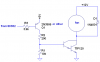
Since 89S52 is a CMOS part, its outputs should swing rail-to-rail with no load (the datasheet says 0.9*Vcc @ 10uA source current). The sink capability is 1.6mA at 0.45V, so you should be able to use a PNP as as a buffer. See below.
An IRF540 Mosfet needs 10V on its gate to turn on completely. A few out of 100 will turn on pretty well with only 5V on the gate. Try a few hundred of them and pick the most sensitive one.
Ahmedragia21, how many of these are you going to build? A good engineering solution is not required for a one-off. If you are going into manufacturing, then your concern is valid. However, if you are going into manufacturing, you shouldn't be concerned about your inability to find a local source.
Roff , why you made a voltage driver using the 10k and the 200 ohm , after calculating the output voltage ,it will be approx 4.9 V , what's the wise for that ?
Roff , why you made a voltage driver using the 10k and the 200 ohm , after calculating the output voltage ,it will be approx 4.9 V , what's the wise for that ?
The base voltage of the TIP120 darlington is a high of only 1.3V, not 4.9V. R1 isn't even needed since the darlington has it built-in.
The 200 ohm resistor R2 applies a base current of 18mA to the darlington to make sure it saturates.
The base voltage of the TIP120 darlington is a high of only 1.3V, not 4.9V. R1 isn't even needed since the darlington has it built-in.
The 200 ohm resistor R2 applies a base current of 18mA to the darlington to make sure it saturates.
I forgot about the internal resistor to GND.
I was using the presumably worst-case numbers mentioned previously: Vbe=2.5V@Ic=3A, and setting forced beta=250.
3A/250=12mA
(5V-2.5V)/12mA~200 ohms.
It is good engineering practice to provide a path for collector-base leakage current, and to discharge base capacitance, providing more rapid turn-off of the Darlington pair when the base current drive is removed.
I've two questions 1st but that scheme will make a voltage divider when the PNP is on , hence there will be a 4.9V on the base of the TIP121 correct ? but how the current will be calculated ?
2nd one is how a uC like 89S52 source and sink two different currents using only one output pin , is it not a simple transistor ?
Audioguru explained the first question. The typical Vbe(on) is around 1.3V (see fig. 2 in the Fairchild TIP120 datasheet). With the PNP driver in saturation (Vce(sat)~0.1V), the current through the 200 ohm resistor will be
Ib=(5-0.1-1.3)/200=18mA,
which will ensure saturation of the TIP120. This is more than the 12mA required, but as I explained previously, was chosen assuming the worst case Vbe(on) is 2.5V, as specified in the datasheet.
Regarding your second question, the 89S52 is a CMOS part, so it has a push-pull output stage. The N-channel pulldown transistor obviously (to me) is a much larger geometry device than the P-channel pullup (the "push" transistor). Larger geometry devices have more drive capability (lower on resistance). A second factor is that, for equal-sized devices, N-channel parts have about twice the drive capability of P-channel. This is why it can sink much more current than it can source.
You never answered this question, which I asked previously:
Ahmedragia21, how many of these are you going to build? A good engineering solution is not required for a one-off. If you are going into manufacturing, then your concern is valid. However, if you are going into manufacturing, you shouldn't be concerned about your inability to find a local source.
Roff, for your question i didnt understand it completley ,im not going to manfucture this product , its just a graduation project and yea we dont have local sources for most electronics parts in the egyptian market .
This site uses cookies to help personalise content, tailor your experience and to keep you logged in if you register.
By continuing to use this site, you are consenting to our use of cookies.