Hey kids,
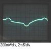
Going by the standard method of doing a transformerless supply, I get my 5V at the zener. On the scope it looks like it should with the positive and negative "camel bumps" from the rectifiers. But overall it's a stable 5V. The problem is, the PIC won't run.
A simple app - push button, LED lights. One button one LED. That's it. No shorts or solder bridges. No complex wiring. The PIC is getting power, the button pin reads 5V open / 0V shorted. The LED lights fine if I touch a 5V wire to it's pin. Nothing is wrong!!! Yet the same PIC popped out and stuck in a breadboard powered by a real regulated supply runs just fine.
Microchip themselves even suggest it's fine to run transformerless 5V supplies:
**broken link removed**
Does anyone have any experience running one this way?