Electro Tech is an online community (with over 170,000 members) who enjoy talking about and building electronic circuits, projects and gadgets. To participate you need to register. Registration is free. Click here to register now.
Welcome to our site! Electro Tech is an online community (with over 170,000 members) who enjoy talking about and building electronic circuits, projects and gadgets. To participate you need to register. Registration is free. Click here to register now.
Depending on the transformer, the resistance of one of the coils may not be that large. You cannot, however, measure a resistance "between" the coils; as the coils aren't connected together (on a regular transformer). If you do measure a resistance, there's a short somewhere. If you can't measure the resistance of one coil or the other, there's likely a break in the coil (maybe the coil on one side or the other was overloaded, and it opened). Finally, if you are able to measure both, and you know what the ratio of the transformer is supposed to be, the resistances measured should follow the ratio; if they don't, there might be a problem.
Finally, if you are able to measure both, and you know what the ratio of the transformer is supposed to be, the resistances measured should follow the ratio; if they don't, there might be a problem.
The ratio of resistances can be a lot larger than the turns ratio, because the winding with the higher number of turns will usually be made out of thinner wire.
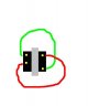
Here is a drawing. The greenline and the red line are the terminals that are connected. It seems like a really weird configuation to me.
2nd Question. According the the schematic and instructions that came with it, the low resistance side is connected to the speakers and the high resistance is connected to SCR's.
The resistances I got were 2ohms and 50 ohms. Wouldn't attaching a 2ohm load to a stereo that already has speakers connected cause the stereo to overheat?
The AC impedance, which the amp sees, is generally much higher than the transformer DC resistance. It depends upon the transformer turns ratio and the load on the transformer secondary. Generally I would expect that to be much higher than your speaker impedance, and thus be a negligible load for your amp.
Possibly, could this particular circuit be the circuit or similar to the circuit you are getting at with T1 being the transformer? T1 is a 10K:600 Ohm Audio Transformer but there are no speakers. There is a Microphone (or audio input) and the transformer secondary is driving the SCRs.
The kit is spec'd for an input of up to 200W. Into 8 ohms the voltage is 40V RMS. The transformer probably steps down this much voltage, and does not step it up. So the transformer is reversed.
Here is a drawing. The greenline and the red line are the terminals that are connected. It seems like a really weird configuation to me.
2nd Question. According the the schematic and instructions that came with it, the low resistance side is connected to the speakers and the high resistance is connected to SCR's.
The resistances I got were 2ohms and 50 ohms. Wouldn't attaching a 2ohm load to a stereo that already has speakers connected cause the stereo to overheat?
I have a transformer that has a similar pinout, it is a step-up transformer for a camera flash circuit(about 3v to 200volts). I bought it from electronic goldmine too, they stated that it has a weird configuration, just like the one you have.
This site uses cookies to help personalise content, tailor your experience and to keep you logged in if you register.
By continuing to use this site, you are consenting to our use of cookies.