Continue to Site

Welcome to our site!

Electro Tech is an online community (with over 170,000 members) who enjoy talking about and building electronic circuits, projects and gadgets. To participate you need to register. Registration is free. Click here to register now.

  • Welcome to our site! Electro Tech is an online community (with over 170,000 members) who enjoy talking about and building electronic circuits, projects and gadgets. To participate you need to register. Registration is free. Click here to register now.

Switching Led

Status
Not open for further replies.

willeng

Member
I require a circuit that switches an LED on at a pre-set voltage & off again if the voltage falls or rises above this this pre-set value.
I thought of using a peak detector circuit which will switch on at the desired value & off again if it falls below this value but I am not sure if this can be configured to go off again if the value rises above the pre-set value?

I would like the circuit to work in a very narrow band & to be fairly precise.
Could someone advise me as to what circuit I require to achieve this?

Basically I am using a differential pressure sensor connected to an instrument amplifier circuit & I want to switch the LED on at the pre-set Pressure & off if the Pressure is above or below this value.
Cheers
 
What supply voltage is available?
What voltage (approx) do you want to switch on/off at?
Do you want a pot to manually set the voltage? or will 1% resistors work? (fixed)
 
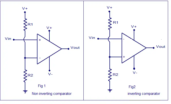
What you are looking for is a comparator, most often implemented using an operational amplifier. The values of R1 and R2 determine the voltage level at which it switches its output.

volatge-comparator.png


Depending on your sensor, though, you may need a preamp, but the above is the basic circuit you'll want to use.

Regards,
Matt
 
Thanks for the quick replies,

The supply voltage is + - 15vdc, I would like to have the voltage switch on/off at 12vdc to give me the option of installing an alarm signal if required later.
Yes I would like to have a multi turn pot to set the voltage manually.

Thanks for the Comparator drawings.

Cheers
 
Sorry for the double post, but doesn't a comparator circuit work like a peak detector where it will just turn on when the input is greater than the reference signal & stay on until the input drops below the reference signal.
In other words it will not turn off if the input signal is greater than the reference signal. I need to switch on when the input signal matches the reference signal & off if the input is Above or Below the reference signal.

Cheers

Ah, I see what you're saying. What you want, then, is a window comparator (it turns on the output only for a small "window", or range of voltages).

Here's the basic circuit, along with some graphs (pulled from Google):

**broken link removed**

When the input voltage is between the two reference voltages, the output will go high. Once the voltage drops below the reference "window" or rises above it, the output will go low.
 
In other words it will not turn off if the input signal is greater than the reference signal. I need to switch on when the input signal matches the reference signal & off if the input is Above or Below the reference signal.

So:
0 to 11.9999 volts = LED off
12.00000V = LED on
12.0001 to 15 volts = LED off

That's not good. What voltage range for the LED on? One volt? or 1/2 volt?
 
So:
0 to 11.9999 volts = LED off
12.00000V = LED on
12.0001 to 15 volts = LED off

That's not good. What voltage range for the LED on? One volt? or 1/2 volt?

Hi Ron, I just posted before your post appeared.
I am not sure what minimum range can be set by a circuit but the range would be best set as tight as possible, say 0.001 to 0.01 if that is possible.

Another question the power supply will be regulated but will Mains Voltage Variation upset a circuit like this?

Cheers
 
R2 sets the V ref1 to V ref2 difference.
A TL431 is a good reference. 2.5V 2.5% or 1%
RL sets the LED current. If the output is low it shorts out the LED and no light. If the output is high then RL powers the LED.
upload_2014-7-4_19-43-7.png
 
Also, **broken link removed**. It provides plenty of examples.

Ron
 
I think your "good" window is so small it will be hard to hit. You don't have a way to know if you are too high or low.
The RED LED is on when the voltage is too high.
The BLUE LED is on when the voltage is too low.
The two GREEN LEDs are on when the voltage is just right. (must use 2 LEDs)
upload_2014-7-4_21-44-57.png
 
You can also always widen the window to, say, 2 volts--1 volt above or 1 volt below (11-13v). You could even use a window of 1V, and have .5v high or low, depending on how precise you're expecting the input to be.
 
Your window is too tight. Now if this was a a "pressure controller" things would be a little different. Maybe, that is what you need?
 
Thanks everyone for the additional information & yes Ron your correct with not knowing if I am above or below the desired setting, the idea with the coloured LEDs is a good one & obviously something I never thought of.
I have been simulating some circuits on Ltspice & realised myself that the window is far to tight considering the manual adjustments that are required to get the correct "Vacuum Pressure" from my machine.
KeepitSimpleStupid, I hope it's ok if I refer to you as T to save me writing your user name all the time & because of other reasons.
Yes your correct, a pressure controller is what is required but they are expensive.
I have been manually adjusting the Vacuum Pressure for many years & it is time for a change.

If you could point me in the right direction I would like to have a go at building a controller, can this be done with Hardware only such as a PI or PID controller?

My machine operates from 240AC so I guess there are two ways of controlling it, firstly by altering the speed of the Motors or by using a Servo Valve to restrict a conduit to obtain the correct pressure?

Any advise would be greatly appreciated.

Cheers
 
OK, so what you are really looking to do is control vacuum pressure in a vacuum tank or manifold. You have a delta p sensor that looks at atmosphere likely on one port and vacuum on the other port. The sensor has an output that is, based on earlier post amplified and the goal is to use the amplified voltage from the sensor (vacuum transducer) to maintain a vacuum pressure. Would that be correct? Now if that is correct then the sensor model and type need known with a data sheet for the sensor and exactly what the amplification is off the sensor. Range and output so the actual scaling is known.

As to actual control? The type control is normally dictated by how tight the control needs to be and how precise. For example the basic on/off control using a solenoid valve is inexpensive but not very precise. If you are just maintaining a vacuum in a vacuum chamber, auto-clave device, vacuum oven or furnace this may be all you need. Other applications require tighter control like PID loops and such. So the application really needs well defined. A good start is at present you are manually controlling and have been apparently for years. Exactly how? Turning vacuum pump on/off or manually opening and closing a valve?

Ron
 
I've actually written two of them. One was an 7 loop controller that did Power, voltage, current and temperature control simultaneously with a lot of neat stuff. The second used the proportional band of of one as the output element and an IEEE-488 RTD thermometer as the input element. The latter was in BASIC and the former FORTRAN.

Now, autotuning. I would not have a clue.

welling: KISS is OK too.

Another control method MIGHT be pulse width modulate an orifice.

Budget and what do we have to work with?
 
Thanks for the replies once again,

This morning I will get some specifications of what I have & my control method & post the details when done.

Cheers
 
I went to ebay and used the search term for "process controller" and got this hit: **broken link removed**

Since I've had to select a fair number of temperature controllers, I know what to watch out for, The model numbers can be daunting and SOME are re-configurable to nearly anything. Fortunately, I made a selection that served where I worked very well. We had to make choices when the older type became obsolete and newer models used more standard control signals.

Then I changed the game entirely. when I proposed it, I was given "Will you guarantee it will work?" and I said yes. Isolated output was mandatory.
 
Status
Not open for further replies.

Latest threads

New Articles From Microcontroller Tips

Back
Top