Continue to Site

Welcome to our site!

Electro Tech is an online community (with over 170,000 members) who enjoy talking about and building electronic circuits, projects and gadgets. To participate you need to register. Registration is free. Click here to register now.

  • Welcome to our site! Electro Tech is an online community (with over 170,000 members) who enjoy talking about and building electronic circuits, projects and gadgets. To participate you need to register. Registration is free. Click here to register now.

Switch a power supply on and off with a TV?

Status
Not open for further replies.

AznGothic

Member
I have some LED lights that I will be wiring up to a laptop charger that is 120VAC input, 12VDC 4A output. I want these lights to come on and turn off when I turn on and off my TV. Looking at the logic board in the TV, I see a connector with pins going to the TV's power supply labeld 12V, GND, ADJ and ON/OFF. I tested these pins and found the 12V stays on all the time and the ON/OFF gets 5V when you turn the TV on and goes dead when you turn the TV off. Is there a way for me to get the TV to turn the LED power supply on and off? Perhaps cut the 120VAC input line for the power supply and put a relay in there that is tied to the 5V ON/OFF pin in the TV? And which relay would I need to buy to do this? I looked at digikey and I just don't understand all of the relay terminology. I'm assuming what I need is the "Power Relay, Over 2A" and not the "Signal Relay, Up to 2A" but then it talks about coil type, coil current, contact rating, switching voltage, turn on voltage (max), turn off voltage (min).....what? If the idea of putting a relay on the ON/OFF pin to supply 120VAC to the LED power supply would work...I just need the coil to turn the relay on and off using 5VDC and the relay needs to handle 120VAC.

Is this a good way to do it or is there a better way? And what relay do I need to purchase if this is the way I should do it?
 
I am not sure exactly where you are going with all of this? If you have an always on 12 volt source (that is not through a pull up resistor) and you have a 5 volt source that turns on/off with the TV and you only want to have a few LEDs on when the TV is on there must be a dozen simpler ways to go about it. If they are just small generic LEDs why not use a transistor to turn them on and off? If you plan to use the laptop charger for much else then just use the 5 volts to turn on and off a SSR (Solid State Relay) and let the SSR turn the laptop charger on and off? You really need to provide much more information about your objective. Also keep in mind if this TV has any warranty it will be gone as soon as you tamper with the TV.

Ron
 
When I worked with video conferencing I fastened a photo-isolator over the On indicator LED of a TV. Then my load and power supply were isolated from the mains.
 
When I worked with video conferencing I fastened a photo-isolator over the On indicator LED of a TV. Then my load and power supply were isolated from the mains.

That would be a good way to go. Ideal isolation and no intrusion into the TV set.

Ron
 
The TV does not have any warranty. I would also like to stray away from having something visible in front of the TV that's turning the LED's on and off. The LED's are 12VDC and are pulling roughly 2.6A. Reloadron, what you said about using an SSR to turn the laptop charger on and off is exactly what I was asking about. I wanted to make sure running a relay on the 5V ON/OFF pin of the TV power supply to switch the 120VAC of the laptop charger on and off would be ok. And I was asking about the relay terminology on digikey because I don't undnerstand it completely and want to make sure I get the correct relay. I'm not sure how much more info I could give? What are you needing to know or what are you confused about? I just simply want to hit the power button on my TV's remote control and when my TV turns on, it also turns on the LED's behind the TV that are powered by a 12VDC 4A laptop charger.
 
OK, if you want to go that route I would use a SSR (Solid State Relay) as I mentioned. The power supply (laptop charger) you are using will draw very little mains current. A mechanical relay would work but I would go the SSR route. You want a SSR with a control voltage like 3 to 32 volts (very common) that will switch a 120 VAC (most are 90 to 240 VAC) at actually less than 5 amps (actually much less based on what you want to power). They are made by a host of manufacturers, Crydom comes to mind. If you go the mechanical relay route you mentioned the 5 volts turns on and off so any small relay with a 5 VDC coil that has contacts that will handle around 5 amps ac @ 120 VAC. The relay coil will draw a little current and there is no easy way to tell if the 5 VDC power you found will support it other than guess it will. Since you mention 120 VAC I'll assume you are in the US. If getting a SSR is a problem I likely have several in my junk parts laying around. Yours for the asking.

Ron
 
You can buy slave power boards that will do what you're after, e.g. https://www.ebay.com.au/itm/Smart-P...ing-Power-Board-with-LCD-Screen-/121386414124

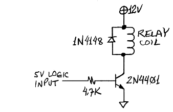
As mentioned above, the 5V ON signal is quite possibly incapable of driving a relay directly. You can use a transistor to buffer it, as shown below. The relay would have a 12V coil, with contacts rated for 120VAC or higher, and a moderate current.
2N4401drivingRelay.jpg
 
I posted this in a different forum as well cause I didn't know if one or the other would flag me (I've been flagged on the other forum in the past for posting a question that apparently violated their policies because it had to do with automobiles.) After talking to a few people though I'm wanting to go the SSR way. I've been looking on digikey for one but every one I find that looks like it would work says out of stock. Perhaps I'm just putting in the wrong filter options. I'm sorry if I seem a bit dumb in this area but I'm still learning and the terminology used on digikey is confusing the crap out of me.

I believe the power supply said Input: 120VAC 1.5A Output: 12VDC 4A. So I just have to make sure the SSR can handle the 1.5A right? One thing that is confusing me is the ones I'm looking at say Voltage Input 1.2VDC. But the pin I'm going to use puts out 5VDC. So wouldn't I need the SSR's voltage input to be 5VDC?

Here's what I was looking at:
https://www.digikey.com/product-detail/en/S202S01F/425-2402-5-ND/720462
 
You can buy slave power boards that will do what you're after, e.g. https://www.ebay.com.au/itm/Smart-P...ing-Power-Board-with-LCD-Screen-/121386414124

As mentioned above, the 5V ON signal is quite possibly incapable of driving a relay directly. You can use a transistor to buffer it, as shown below. The relay would have a 12V coil, with contacts rated for 120VAC or higher, and a moderate current.
2N4401drivingRelay.jpg
That is a very awesome power strip. I had no idea they made those. It would definitely work for what I'm trying to do and I appreciate the link. But it would kill the fun of learning and doing. I might pick one up for future projects but for now I would rather not take the easy road out.
 
One thing that is confusing me is the ones I'm looking at say Voltage Input 1.2VDC. But the pin I'm going to use puts out 5VDC. So wouldn't I need the SSR's voltage input to be 5VDC?
The 1.2V is the voltage of the LED in the SSR, you just need to add a series resistor to run it from 5V. A 270 ohm resistor will give you 14mA drive current from 5V.
 
But it would kill the fun of learning and doing. I might pick one up for future projects but for now I would rather not take the easy road out.
Better than killing the fun of being alive if you aren't comfortable working with 120VAC.
 
I see Crydom D2410 Solid-State Relays 240VAC 10A 3-32VDC on Ebay as low as about $4.00 US which would work. New they can be expensive but there are plenty of used ones very inexpensive to be had. Very simple to use and using a SSR will give you isolation. There are literally dozens of SSRs that will work. Crydom is just an example.

Ron
 
Better than killing the fun of being alive if you aren't comfortable working with 120VAC.

I use to work for Texas Electric installing 14,400V transformers and 120/240V meter's on houses. So no worries there. I just don't understand all the relay terminology like my question above about the 1.2V thing.
 
I see Crydom D2410 Solid-State Relays 240VAC 10A 3-32VDC on Ebay as low as about $4.00 US which would work. New they can be expensive but there are plenty of used ones very inexpensive to be had. Very simple to use and using a SSR will give you isolation. There are literally dozens of SSRs that will work. Crydom is just an example.

Ron

Would I really need something that heavy duty instead of one of the smaller ones like I linked? (Not sure how big that actually is but it looks huge!)
 
One thing that is confusing me is the ones I'm looking at say Voltage Input 1.2VDC. But the pin I'm going to use puts out 5VDC. So wouldn't I need the SSR's voltage input to be 5VDC?

Ah yes, that 1.2 volt thingy. What they are telling you is that the forward voltage for the internal LED (inside the SSR) is 1.2 Volts and they tell you the If (Forward Current) is 20 mA. So to drive the device with 5 volts things look like this.

5.0 - 1.2 / .020 or Vsupply - Vfwd / I fwd and that gives us 5.0 - 1.2 = 3.8 / .020 = 190 Ohms so you would place about a 190 ohm in series with the SSR. However, 190 isn't a common value so you would use a 200 Ohm resistor. Does that make sense?

Ron
 
Would I really need something that heavy duty instead of one of the smaller ones like I linked? (Not sure how big that actually is but it looks huge!)

The one you linked to will do fine. I covered the 1.2 volt thingy above. Some SSRs can use a wide range of input voltage while the ones like you linked to need an external resistor on the control voltage side.

Ron
 
Here is an example of what you would have:

SSR Example.png


D1 is just a diode to prevent reverse voltage to the control lines, a 1N4002 or similar would work fine. R1 is the either 180 or 200 ohm resistor we mentioned earlier. Your +5 Volts On/Off would connect to R1 where it is labeled Vcc. TR1 and the V1 input get eliminated and pin 4 of the SSR goes to ground. The Load is your power supply and Zs is a snubber for transient spikes which you can likely omit or hack a snubber out of an old power strip.

Ron
 
Ok, for the equation you gave me, where did you get the number .020? I know resistors would decrease the voltage but I never knew how to figure out which resistor to use to get a certain value. And using the resistor would also limit the current draw off of the 5V pin correct? The diagram makes sense to me so thank you for that. Also do I need to mount this on a heat sink?
 
Last edited:
OK, here is what is going on. First, a LED is a current device so hold that thought. Now inside the SSR is a LED and in this case according to the data sheet that LED has a forward working voltage of 1.2 volts which is pretty typical and a forward working current of 20 mA or .020 Amp. If we were to directly apply 5 volts across the LED it would draw much greater current and burn up. So we need to limit the LED current. In this case limit that current to 20 mA. We know the LED forward voltage drop is 1.2 volts so if we apply 5 volts we can say 5.0 - 1.2 = 3.8 Volts. Therefore I can say 3.8 Volts / .020 Amp = 190 Ohms. This all goes back to Ohms Law.

So now if we look at the circuit I posted above if resistor R1 is dropping 3.8 Volts and the SSR internal LED is dropping 1.2 Volts there is our 5.0 volts and the circuit current will be 20 mA. The small problem is that 190 Ohms is not a common off the shelf resistor. Common off the shelf values would be 180 Ohms or 200 Ohms. We could get by using either value. Generally the next higher value is selected so we would use 200 Ohms. Doing so will slightly lower the current but not enough to likely matter.

Yes, the current draw off the 5 volt pin or 5 volt supply will be limited to 20 mA.

Ron
 
Last edited:
A lot of modern TVs have a relay to connect power to the main power supply. That is what make the click when they turn on. The receiver for the remote is left on all the time, run from a separate, much smaller, power supply. This keeps the power low.

If that is the case in your TV, you could just run the power supply for the LEDs from that same relay.
 
Status
Not open for further replies.

Latest threads

New Articles From Microcontroller Tips

Back
Top