Continue to Site

Welcome to our site!

Electro Tech is an online community (with over 170,000 members) who enjoy talking about and building electronic circuits, projects and gadgets. To participate you need to register. Registration is free. Click here to register now.

  • Welcome to our site! Electro Tech is an online community (with over 170,000 members) who enjoy talking about and building electronic circuits, projects and gadgets. To participate you need to register. Registration is free. Click here to register now.

stripboard layout

Status
Not open for further replies.

newbie73

New Member
hi all i need help again!!

i have this circuit drawing, which im sure is really easy to put together but i just cant workout the stripboard layout!! im new to electronics and have read a few sites about how to read a circuit drawing but i just cant seam to get my head round in when i come to making. i get the thory but the practical is ....well crap!!

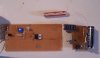
can someone please show me how this circuit should be layed out and how to connect up the scr.

also are there any good websites or books that actually teach you how to read and understand circuit drawings, every site iv seen so far say "join the dots and there you go!!!" which is not much help.

thanks for the help
 

Attachments

  • PGTRANS.gif
    PGTRANS.gif
    5.3 KB · Views: 524
newbie73 said:
thanks gayan,

the info on the scr was very usefull, but i still cant get the circuit to work, any ideas?

hi,

What are you expecting the circuit to do?:confused:
 
Last edited:
hi eric,

its just a simple photo flash trigger, the beam is broaken which sets off the scr and in turn sets off the flash light.

thanks for the ad on to the circuit
 
newbie73 said:
hi eric,

its just a simple photo flash trigger, the beam is broaken which sets off the scr and in turn sets off the flash light.

thanks for the ad on to the circuit

hi,
You do realise that once the SCR is triggered it will remain ON?
The only way to switch it OFF is to interrupt the Vload voltage.

If its still not working, measure a few voltage points on the circuit, add them to the drawing and post it.
Eric
 
hi eric,

yep i know it will sta open, thats cool for what im doing.

i cant measure voltage as i dont have a meter to do so with (must get one)

i have tried to make it on a breadborad and no luck, i have followed bread board layout circuits before with good results, but a have no idea how to lay this or any circuit out on stripboard.

cheers
 
hi,
Copy and use this strip board GIF.

Eric
 
Last edited:
hi eric,

cheers, i have some stripboard images but the trouble is i cant work out where or how all the parts go together. all the sites iv read about converting circuit drawings into stripboard layouts are no use at all, they all just say join the dots which is no go for the beginner.

also i have an tic116d type scr so not sure if it will work with that type?

do you know of any good sites that actually teach you how to transfer circuit drawings into stripboard layouts???

cheers
 
newbie73 said:
hi eric,

cheers, i have some stripboard images but the trouble is i cant work out where or how all the parts go together. all the sites iv read about converting circuit drawings into stripboard layouts are no use at all, they all just say join the dots which is no go for the beginner.

also i have an tic116d type scr so not sure if it will work with that type?

do you know of any good sites that actually teach you how to transfer circuit drawings into stripboard layouts???

cheers
hi,
Does this help as a starting point?

Eric
 
Last edited:
thank you eric, that helps a lot. i just wish i could work out how to lay it out on my own. do you know of any good books or sites i can learn how to do that.

cheers, and thank you once again
 
hi

right iv built the circuit but it still wont work. im not sure if i got the pot mounted correctly but the rest is set up exactly the way it is in the layout any idears!!!!!

cheers
 
ok here are some pics of my set up.

i need the circuit to , when the beam is broaken turn the flash unit on = the flash unit then powers the EM coil or at least dumps its power through the coil.

can some one please tell me where im going wrong, and please use very basic terms and drawings as i really cant get my head round electronics, but i will!!

break beam fire coil from flash unit, thats it!!

any help would be very gratful,

best regards
 

Attachments

  • 000_0581.jpg
    000_0581.jpg
    404.5 KB · Views: 361
newbie73 said:
can some one please tell me where im going wrong

The resistor on the right ( in your picture ) goes straight to the negative side of the battery, and it shouldn't.

If that doesn't help, post a picture of the other side of the board.
 
newbie73 said:
ps the red and black fly leads on the left of the pic go to the +9v power, the flash unit has its own power

Hi,

Look at this pic.

Eric
 
Last edited:
hi eric,

doh awnsers:
1) the c of the transistor is connected to the + power
2) yep i need to keep out ambiant light - doh will do
3) gate was grounded..

thanks
 
hi all,

yep im back again, and yet again i just cant get this circuit working, im getting to the point that i am willing to pay someone to make a mock up for me so i can just copy it!!!

so if any one is intrested please get in contact, i just dont have the time to try and work this out anymore.

cheers
 
Status
Not open for further replies.

Latest threads

New Articles From Microcontroller Tips

Back
Top