Continue to Site

Welcome to our site!

Electro Tech is an online community (with over 170,000 members) who enjoy talking about and building electronic circuits, projects and gadgets. To participate you need to register. Registration is free. Click here to register now.

  • Welcome to our site! Electro Tech is an online community (with over 170,000 members) who enjoy talking about and building electronic circuits, projects and gadgets. To participate you need to register. Registration is free. Click here to register now.

Solved PIC Frequency counter - Interesting quandary

augustinetez

Active Member
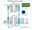
I have 2 16F628A based Frequency counters, both using exactly the same code except one is using an external OCXO as the frequency ref and the other is using a 10MHz xtal.

Feeding 10MHz in (from the OCXO) to the xtal based unit and it reads 20MHz, feeding the same signal to the OCXO based unit and it reads correctly at 10MHz.

The only difference between the two units are slight differences in component values of the input circuit as below. Input stage 1 is the 10MHz xtal version and Input stage 2 is the OCXO version (and yes, the input stage really needs updating to something better - on the 'todo' list).

Any one seeing something I'm not (apart from the 270Ω resistor in one of the units) ?
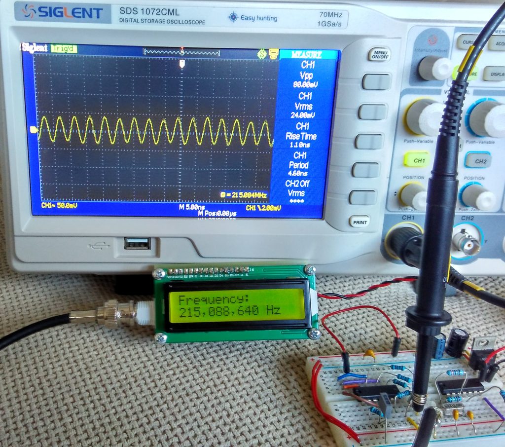
Input.jpg
 
I agree with Mike, first thing confirm that the PIC is actually running at 10MHz.

Other than that, I'm not very happy about how you're feeding the signal to the PIC, if you're not supplying a decent logic level square wave to it the input could be detecting spurious pulses if it's sitting around the threshold level.
 
Are you able to blink an LED with both units to confirm they're running at the same speed?

Mike.
Yea, I can do that, I did think maybe it might be running at the wrong speed.

Other than that, I'm not very happy about how you're feeding the signal to the PIC, if you're not supplying a decent logic level square wave to it the input could be detecting spurious pulses if it's sitting around the threshold level.
These were a quick and dirty lashup to do a job a while ago, as mentioned, a better front end is on the list to tart them up some.

Looking at the voltage on the output, it is more than likely now you mention it that it is spurious rubbish triggering it.
 
Sim looks like very small differences, for sine input, (2 graphs, 100 mV and 1V Vin) :

1695724761357.png


But notice the V into PIC out of spec.....? Note C2, C4 parasitic C of layout and PIC input. Is
there a prescaler chip between this input circuit and PIC ?

Square wave input, 1V -

1695726143261.png


Not sure how accurate this sim is at RF. Verification with scope prudent. FET probe.


Regards, Dana
 

Attachments

  • 1695725475534.png
    1695725475534.png
    61.1 KB · Views: 91
  • 1695725849729.png
    1695725849729.png
    189.6 KB · Views: 101
Last edited:
You might have a look here:


Which uses a high speed comparator to drive the PIC.

The original antique MicroChip version used a schmitt trigger to do a similar job:


(not the original application note, but the updated weeder version with an LCD).
 
If you have a suitable oscilloscope, follow the test signal from the input to the counter and through the first stages to the gate to ensure that it is really a 10MHz signal all the way.

Many years ago before I owned a 'scope, I was experimenting with an existing 100kHz crystal oscillator and some TTL dividers (7490) in order to make a versatile crystal calibrator.
Whatever I did to the circuit, I could not get the correct division ratio and so I just abandoned the project.
A few years later when I had my first 'scope, I revisited the project, and found the problem very easily...

The output from the crystal oscillator was a distorted sine wave. The distortion was such that the waveform crossed the 0 volt value twice, due to very high 2nd harmonic content.
Listening to the 100kHz in a receiver, it was 100kHz.
But to a TTL IC it was 200kHz.

If I had just taken the thing to work and looked at it on the scope, I could have easily sorted the problem and made a nice crystal calibrator.

So, how is your test signal?

JimB
 
And the answer to that question is:

The output of the OCXO is a dirty square wave - bit of ripple top and bottom (so will need to make an output buffer/conditioner for it - another 'todo' job :banghead: ).

At the junction of the 15k bias resistor, 10uH and 470R resistors it is a reasonable (ish) sinewave but at the collector it is a dirty square wave again and yes, the scope is reading it as 10MHz all the way through.
 
OK
A good idea while it lasted.
Jim GM3ZMA
 
I had a thought that maybe the missing 270Ω resistor "might" have had something to do with it, but not the case (I added it).

Also adjusted the bias so that the input to the PIC sits at 2.2V with no signal, so should now be well above the threshold.

Haven't done the flash the LED bit yet, but scoping the 10MHz xtal shows it running at the right frequency on the scope.

Hope I can find this magic frequency doubler, could come in handy in other projects :)
 
Hehe, dumb error - usual PIC frequency counter method of using one pin to shunt the count input to ground to stop counting - guess who didn't connect the pins together :sorry:
Actually, that wasn't the reason for doing so - the original app. sheet used a PIC with minimum specifications (all there was way back then), and the 16 bit timer used was effectively write only - so the paired pin was used to manually clock the timer, and count how many clocks it took before it rolled over, and thus calculate what value was in it.

With a modern PIC you can read various of the timers without issue, and simply turn them OFF and ON in software.
 
...so the paired pin was used to manually clock the timer, and count how many clocks it took before it rolled over...
With a modern PIC you can read various of the timers without issue...

Doesn't that have to do with the fact that it's using a prescaler, and since you can't read the prescaler count it does that manual toggle thing to be able to count how many clocks the prescaler has seen so you can get an accurate count?
 
Doesn't that have to do with the fact that it's using a prescaler, and since you can't read the prescaler count it does that manual toggle thing to be able to count how many clocks the prescaler has seen so you can get an accurate count?
Perhaps, it essentially works as a 16 timer with only 8 bits accessible - going from memory from a few decades ago :D
 
Hehe, dumb error - usual PIC frequency counter method of using one pin to shunt the count input to ground to stop counting - guess who didn't connect the pins together :sorry:
That's actually an extremely old method. More recent methods use a single pin for input and simply change the data direction to 'output' at the end of the 'gate' period. Then you pulse the timer edge select bit until a timer overflow to extract an 8-bit value from the prescaler. I have example code if you need it...

BTW, I came across an interesting "dual 16-bit counter" IC awhile back that might make a nice 100-MHz Frequency Counter.
 

Attachments

  • Freq Counter.jpg
    Freq Counter.jpg
    270.6 KB · Views: 129
Last edited:
If using TMR0, you don't even need to change the pin to input - TMRO will still count if the pin is set as an output and set high.

To stop counting you just set the pin low and clock the prescaler as you describe above - check out Phil Rice's frequency counter https://sites.google.com/site/vk3bhr/home/fm2

One thing I have found with this method (fiddling with it now for another project), which may depend on the particular PIC used, is that the usual 470Ω resistor feeding the TMR0 input pin, needs to be higher in value, 1kΩ seems to be about right.
 
If using TMR0, you don't even need to change the pin to input - TMRO will still count if the pin is set as an output and set high.

To stop counting you just set the pin low and clock the prescaler as you describe above - check out Phil Rice's frequency counter https://sites.google.com/site/vk3bhr/home/fm2
That's a trick I haven't seen before. I'll have to try this.
One thing I have found with this method (fiddling with it now for another project), which may depend on the particular PIC used, is that the usual 470Ω resistor feeding the TMR0 input pin, needs to be higher in value, 1kΩ seems to be about right.
I also used a 1K resistor on the T0CKI input on my counters.
 

Latest threads

New Articles From Microcontroller Tips

Back
Top