Continue to Site

Welcome to our site!

Electro Tech is an online community (with over 170,000 members) who enjoy talking about and building electronic circuits, projects and gadgets. To participate you need to register. Registration is free. Click here to register now.

  • Welcome to our site! Electro Tech is an online community (with over 170,000 members) who enjoy talking about and building electronic circuits, projects and gadgets. To participate you need to register. Registration is free. Click here to register now.

Slewing sensor using potentiometer

Status
Not open for further replies.

Sam1920

New Member
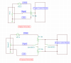
I am trying to slew a vacuum sensor in my car. My trouble is, when I use a single potentiometer I can only slew the lower range of the 5V input signal, that is, turning a 10k pot from 0 - 100%, the signal can only be slewed from 0 - 2.5V. My original design is shown above in the first image. I was feeding the wiper directly into the ECM.

I would like to use the entirety of the input signal, 0 - 5V. So I thought up this quick configuration of using 2 10k 10 turn pots along with 2 double pull single throw switches to capture the entire range. My thought process was that the lower pot would encompass the 0 - 2.5V range, as before, as it is tied directly to ground, and when I wished to slew above 2.5V, the switches would be thrown allowing the upper voltage ranges to be slewed as it is connected directly to the 5V ref line.

I'm not sure this will work or if anyone has a better solution. Can anyone explain why my first idea did not work. I have some working knowledge of basic circuit elements. I appreciate any assistance. Thank you.
 

Attachments

  • BBVS_Schematic2.PNG
    BBVS_Schematic2.PNG
    26.6 KB · Views: 170
When you say "slew" what exactly are you looking to do? Do you mean you want to offset the output of the vacuum sensor or maybe extend the range of the sensor. For example if the sensor has an output range of 0 to 2.5 volts do you want to offset that to like 2.5 to 5.0 volts or something in between? Changing the range would be taking a sensor with a 0 to 2.5 volt output and making it like 0 to 5 volts. Either way the best approach would likely be to use an opamp circuit. I am just not sure what you want with "slew".

Ron
 
Thanks for the response, Ron. By slew I mean offset the output of the current vacuum range, which is about 0 - 5V. However, it would be neat to try to extend the range as well. Maybe I will also look into that. For now, I was just hoping to slew the sensor within its present range of operation. So when it reads 2.5V, slew that by some percentage in either direction. I thought a pot would work for this, but I'm not getting results I expected.
 
What is the output impedance of your sensor? Can you post a link to its datasheet?
 
The part is very old and I'm having trouble finding the datasheet. I was able to find a datasheet for the same kind of part (both made by Bosch) with a similar part number (a more current version I assume is available now). It says load impedance is >50k Ohms. I will continue searching for the actual datasheet or possibly determine output impedance through experimentation. Here is the link: **broken link removed**
 
It says load impedance is >50k Ohms.
That means your 10k pots are loading the sensor too much. BTW, load impedance and output impedance are not the same thing.
 
Are you sure your sensor is putting out an actual 0 - 5 volt signal and not a pulse width modulated or variable frequency type signal?

Very few auto manufacturers ever used a basic 0 -5 volt type sensor signal systems for sensors due to it being way to easy for it to pick up electronic noise from the rest of the engines electronics.
 
I am looking into this now. I understood the sensor to read a pressure which is then converted to a 0-5V signal. I'll write back as soon as I figure this out.
 
Ohh, ok. And thank you for telling me that. I will look up the difference now.

The sensors you linked to appear to output an analog voltage per tcmtech's post. Really depends on the automotive system used. While far from a guru on this stuff here in the US many Ford products use the digital output sensors while GM products lean towards analog output sensors. I assume the sensor in question is a MAP (Manifold Absolute Pressure) sensor? Something else to consider is the ECU (Engine Computer) is looking for a specific signal proportional to pressure. Not sure how things will react if the ECU sees something other than expected? Again tcmtech is very up on this automotive stuff and makes a very good point as to what the sensor output actually is so you need to be real sure.

The sensors you linked to are designed to work into an impedance greated than 50K Ohms so yes, your 10K variable resistor will load it down.

Ron
 
Almost always, exactly zero and exactly 5V is unobtainable. There is generally an offset in both directions. This comes about because with a 5V power supply, it's very HARD to output 5V when your power supply is 5V, The sensors may actually be linear or 0-100% over say 0.5 to 4.5 V.

Many sensors are also ratiometric to the supply voltage. So, if tey were powered by say 4V, a 2 V signal may be 50% as when they are powered by 5V, a 2.5V signal is 50%. I ignored the endpoints for that exercise.
 
If its an older device then it probably is a voltage out.
Sounds like you need an op amp, an amplifier with a positive gain will decrease the sensors range, and a negative gain with increase it, youcan also add an offset pot to shift the whole scale up and down, its pretty tricky to do.
Messing with the vac sensor by the way isnt a great way of increasing performance, some aftermarket gizmo's claim to improve performance, often false claims, the pcm uses the vac input on a alpha n system to calculate the airflow and therefor calculate the amount of fuel, ie injector on time, a closed loop system which nearly all are monitors the exhaust gas and makes continual corrections, this would cancel out any adjustment you make to the vac signal, until the adjustment gets more than 10% then you'll set a too rich or too lean dtc code.
 
I've confirmed that the sensor outputs a voltage signal. Maybe I will try using a smaller pot as was suggested earlier.
 
Maybe I will try using a smaller pot as was suggested earlier.
No one suggested smaller. Any load you put on the sensor should have a resistance greater than 50k to prevent loading the sensor excessively. But then the engine computer probably needs a source impedance less than 10k for its ADC to work correctly. So you may well need a circuit to buffer the sensor output.
 
Status
Not open for further replies.

Latest threads

Back
Top