Continue to Site

Welcome to our site!

Electro Tech is an online community (with over 170,000 members) who enjoy talking about and building electronic circuits, projects and gadgets. To participate you need to register. Registration is free. Click here to register now.

  • Welcome to our site! Electro Tech is an online community (with over 170,000 members) who enjoy talking about and building electronic circuits, projects and gadgets. To participate you need to register. Registration is free. Click here to register now.

single-sided pcb layout challenge

Status
Not open for further replies.

Mike - K8LH

Well-Known Member
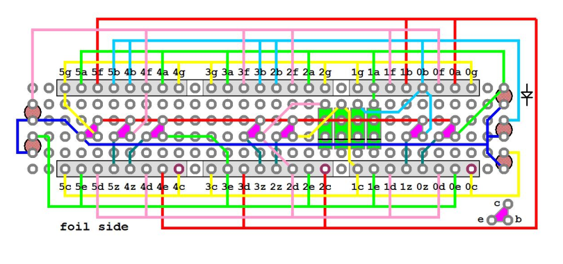
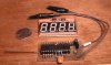
It seems a couple people are interested in building the novelty 1-chip clock so I started building a prototype on a Radio Shack proto' board using #30 Kynar wire-wrap wire. What a pain (grin). I've started wiring the display section of the board per the little drawing below and it occurred to me that one or more of you chaps are probably pretty good at laying out single-sided boards for manufacturing at home. Anyone care to take a stab at it? This is the foil side. The LED single-inline sockets, transistors, discrete LEDs, and diodes are all installed on the other side of the board and will sit underneath the dual-digit LEDs. The PIC, switches, speaker, and relay will be located on the component side of the board too, below the display. I just haven't gotten that far yet.

Later, Mike

clock-1v2-wiring-png.11659


**broken link removed**
 

Attachments

  • Clock-1v2 wiring.PNG
    Clock-1v2 wiring.PNG
    279.9 KB · Views: 1,456
Last edited:
Even at a glance, I can tell it's going to be impossible to do most of that layout in a single layer without a lot of jumpers - just looking at the red, pink, blue, green, and yellow wires connecting all those header pins, forget about a "challenge", it's just plain impossible. You could probably run one down the outside edge of the header, and maybe snake another through between some pins, but there's no way you're getting all 5 of those in there.

Now, as for the challenge of minimizing the number of jumpers required, that's another story... but I expect you're still going to end up with a LOT - this circuit is simply NOT suited for a good single-sided layout, by its very nature.
Though, it looks like it would be very well suited to a double-sided layout...
 
evandude said:
Though, it looks like it would be very well suited to a double-sided layout...
And be prepared for a lot of vias. I made this display board with for digits and it was a good reminder how nice LCD displays are to work with. This board has 2 2-digit 7 segment displays, two switches, and a 16x1 header.

3v0

This is the Mondo SuperProbe. Please, no feedback required on the ceramic osc soldered to the PIC. It is a work in progress. If I build this again I am going to modify the code and replaced the LEDs with a 1 x 24 Character LCD Display Module AllElectronics. https://www.allelectronics.com/cgi-bin/item/LCD-111/365/24_X_1_LCD_.html They are under $2. It looks like the customers at AllElectronics have figured out how to interface to this display in a I2C mode.
 

Attachments

  • Eagle.jpg
    Eagle.jpg
    81.5 KB · Views: 421
  • Probe.JPG
    Probe.JPG
    42.9 KB · Views: 422
Last edited:
This can be done without a huge number of jumpers. I don't have the display defined in eagle and don't have the time right now but here is how I would go about it. This is the top part of the display connected with only one jumper.

Maybe someone could expand on this weaving idea.

Mike.
 
Last edited:
Hmm, didn't really notice before, but the displays are nice and symmetrical about the center - the 4 pins on the left of each side are mirrored from the layout of the other 4... that DOES make the layout a lot easier - good catch Pommie.
 
Mike,

The A-G bus is shared with the RB0-RB6 7-seg common anode gates. How are you gating the segments and displaying the correct digits at the same time? I first thought you might be utilizing the fact that some of the digits only show 0-2, 0-4, 0-5, and 0-9. Since the combination of some gates being turned off forces the segments of particular digits to be turned off, those particular segments never need to be displayed because they are not in that digits range such as 0-2 for the first digit. Is this the case?
 
Donniedj,

Mike came up with a charlieplex type scheme which he described somewhere else. I can't find it at the moment. The secret to the way it works is the line labeled X in the diagram above. The X line replaces the segment line that corresponds to the anode gate line. So, in the left most display the X line will be connected to the A segment replacing RB0. To display a number on the left most display segments that are to be lit are driven low, all other segments are set to input and RB0 is driven high. The same happens for the next display but now X is segment B and RB1 is driven high.

Mike.
 
Mike's got the right idea. The diagram below may help. Each Port B line serves as both a segment driver and as a column driver. The RB0 pin drives the common anode driver transistor on the first display and all of the 'A' segment lines on the other displays. When the first display is being driven "on" by RB0 then the 'A' segment on that display must be driven by the 'X' line which I call the "float" line.
 

Attachments

  • Charlieplexed Display Wiring Notes.JPG
    Charlieplexed Display Wiring Notes.JPG
    181 KB · Views: 387
Aaah I see. I can understand how decades of fueling the 7-segment display industry could evolved into such a clever scheme to get a leg up over the eternal pin count enemy. I was thinking that if Mike K8LH thought this all up on his own, why would he need help with a less mentally challenging task of a layout. :)

I always make all surface mount boards and single sided. So the question of this being a challenge is non existent because for me its mandatory. I would use the suggested weaving techniques along with minumim jumpers by using called out resistors as jumpers and the foot prints of mosfet drivers and jumpers.
 
It's not so much that I need help as it is that I just don't have the facilities to make my own single sided boards.

I'll publish the Clock design and code in the <Projects> forum for those few people who asked me to do so, along with my crude Radio Shack protoboard version, and I thought it would be nice to show a single-sided pcb layout for those people who have the capability to make their own boards.

Thanks for the input guys...
 
Mike,

Where do you get those dual displays from? The only ones I can find have the segments repeated rather than mirrored. If I get time, I might have a go at a single sided layout. If anyone has found a library with a display like the one Mike uses, a link would be appreciated.

Mike.
 
I'm using Fairchild MSD4410C (0.40", CA, Green) or MSD4910C (0.40", CA, HER) on this prototype.

I also have some Fairchild 0.56" dual displays with similar wiring pattern running on other projects; MAN6410E (CA, Green), MAN6910E (CA, HER).

<added>

Sorry, I'm wrong about the 0.56" display pattern (below). It's quite different.
 

Attachments

  • L56.PNG
    L56.PNG
    38.5 KB · Views: 280
Last edited:
Mike, K8LH

Plz share the code here (if u don't mind).

I want to make clock similar to this but with big 7-Segment Display.

I will make my self a Big 7 Segment Display with LEDs.

Thanks.
 
I want to make Real time clock using PIC16F877A.( Clock Frequency 20 MHz.)

I want to ask that TMR0 or TMR1 or TMR2 interrupt is not enough accurate for time(1 Second)...

Or What is the best way for making an accurate time delay???

Thanks.
 
Any of the timers are accurate enough, it simply depends on the accuracy of your clock crystal, and the skill of your programming - as usual I would suggest using timer2, as it's so easy, and I've even posted timer2 RTC code on here in the past.
 
Ayne said:
I want to make Real time clock using PIC16F877A.( Clock Frequency 20 MHz.)

I want to ask that TMR0 or TMR1 or TMR2 interrupt is not enough accurate for time(1 Second)...

Or What is the best way for making an accurate time delay???

Thanks.


Your clock will drift over time due to temperature variations and a stock standard error rate with the crystals

You could use the DS1307, is a lot more accurate with a 32.768Khz crystal, I've done an example with it in swordfish that **broken link removed**

The DS1307 will store and maintain Hours, Minutes, Seconds, DayOfWeek, DayOfMonth, Month and Year information, and will accommodate for leap years, further more, it can run in "battery mode" (if Pin 3 > Pin 8's voltage) and consume less than 500nA.

TMR2 would probably be the best timer for a job like this with the PIC though, I'd do something like this in Swordfish;

Code:
Device = 18F452
Clock = 20

#option LCD_DATA = PORTC.4
#option LCD_RS = PORTC.2
#option LCD_EN = PORTC.3

Include "LCD.bas" 
Include "utils.bas"
Include "convert.bas"

Dim 
    TMR2_Int_Enable As PIE1.1,    // TMR2 interrupt enable
    TMR2_Overflow As PIR1.1,      // TMR2 overflow flag
    TMR2_On As T2CON.2,           // Enables TMR2 to begin incrementing
    mS As Word,                   // Time Registers
    S As Byte,                    //
    M As Byte,                    //
    H As Byte,                    //
    S_Poll As Byte                //

    
Interrupt TMR2_Interrupt()
    Save(0)
    If TMR2_Overflow = 1 And TMR2_Int_Enable = 1 Then
        TMR2_Overflow = 0                           // Reset TMR2 Overflow flag
        mS = mS + 1
        If mS = 1000 Then                           // Code for current time
            mS = 0
            S = S + 1
            If S = 60 Then
                S = 0
                M = M + 1
                If M = 60 Then
                    M = 0
                    H = H + 1
                    If H = 24 Then
                        H = 0
                    EndIf
                EndIf
            EndIf
        EndIf
    EndIf
    Restore
End Interrupt

Private Sub TMR2_Initialize()
    TMR2_On = 0               // Disbale TMR2
    TMR2_Int_Enable = 0       // Turn off TMR2 interrupts

    INTCON.6 = 1              // Peripheral Interrupts Enabled       
    T2CON.0 = 1               //  00 = Prescaler is 1
    T2CON.1 = 0               //  01 = Prescaler is 4
            	              //  1x = Prescaler is 16 
    PR2 = 249                 // TMR2 Period register PR2   
    T2CON.3 = 0               //  0000 = 1:1 postscale
    T2CON.4 = 0               //  0001 = 1:2 postscale
    T2CON.5 = 1               //  0010 = 1:3 postscale
    T2CON.6 = 0               //  1111 = 1:16 postscale    
    TMR2 = 0                  // Reset TMR2 Value    
    TMR2_Int_Enable = 1       // Enable TMR2 interrupts
    TMR2_On = 1               // Enable TMR2 to increment
    Enable(TMR2_Interrupt)
End Sub


// Start of program...
DelayMS(200)                  // Allow LCD to warm up
SetAllDigital                 // Make all pins digital I/O's
Cls                           // Clear the LCD screen


LCD.WriteAt(1,1,"Time")       // Send some text to the LCD

mS = 0                        // Reset all registers
S = 0                         //   (to current time) set time
M = 30                        //
H = 12                        //
S_Poll = 0

TMR2_Initialize               // Turn on TMR2 (with settings for 1mS interrupt)

While True
    If S <> S_Poll Then
        LCD.WriteAt(1,6,DecToStr(H,2),":",DecToStr(M,2),":",DecToStr(S,2))
        S_Poll = S
    EndIf
Wend

The TMR2 is interrupt driven and accommodates for around 5000 cycles between interrupts. Further more the system registers used by the compiler are saved and then restored to ensure no corruption occurs (as the interrupt could happen at any time) See attachment 1
 

Attachments

  • 18F TMR2 Time Example.JPG
    18F TMR2 Time Example.JPG
    35.4 KB · Views: 253
I Found this in Microchip NOTES:-

Real-Time Clock
A real-time clock is implemented using Timer1. The
real-time clock keeps track of the present time using a
routine called UpdateClock. It also determines the
rate that the buttons are read by a routine called
ScanKeys.
Timer1 is set to cause an interrupt each time it
overflows. By adding a specific offset to Timer1 each
time it overflows, the time before the next overflow can
be precisely controlled. The button reading routine,
ScanKeys, is called each time a Timer1 interrupt
occurs. Since ScanKeys performs debouncing of the
button presses, a suitable rate to check the buttons is
once every 25 ms.
With a 32 kHz crystal, the counter increments once
every 31.25 μs when the prescaler is set to 1:1. In order
for Timer1 to generate an interrupt once every 25 ms,
TMR1H:TMR1L are pre-loaded with 0xFCE0h.
The Timer1 interrupt interval, or tick, can be seen in the
following equation:
(FFFFh – FCE0h)*1/32 kHz = .025 s = 1 tick
Each time ScanKeys is called (every 25 ms), it calls
UpdateClock. UpdateClock keeps track of the time
unit variables: ticks, seconds, minutes, and hours.
Since every 25 ms equals one tick, seconds are incremented
every 40 ticks. Minutes and hours are
incremented in a similar fashion.

What u say that how much Timer1 drift in one year?? (ur experience).. (Timer1 using clock crystel 20Mhz.

I don't know that "DS1307" is available in our local market or not.. If it will be available then i will use this.. (i will go to shop tommorow)
 
Gramo all your answers always have a BASIC reference in them, it reminds me of Toastie the Talking Toaster from Red Dwarf (an intelligent toaster with a toast fixation) :)


Toaster: Howdy doodly do. How´s it going? I´m Talkie, Talkie Toaster, your chirpy breakfast companion. Talkie´s the name, toasting´s the game. Anyone like any toast?
Lister: Look, I don´t want any toast, and he doesn´t want any toast. In fact, no one around here wants any toast. Not now, not ever. No toast.
Toaster: How ´bout a muffin?
Lister: Or muffins. We don´t like muffins around here. We want no muffins, no toast, no teacakes, no buns, baps, baguettes or bagels, no croissants, no crumpets, no pancakes, no potato cakes and no hot-cross buns and definitely no smegging flapjacks.
Toaster: Aah, so you´re a waffle man.

. . . . .

Toaster: I toast, therefore I am.

. . . . .

Toaster: The question is this: given that God is infinite and that the universe is also infinite, would he'd like a toasted tea-cake?

. . . . .
Toaster: What´s the point of buying a toaster with artificial intelligence if you don´t like toast?
Lister: I do like toast.
Toaster: This is my job. This is cruel, just cruel.
Lister: Look, I´m busy.
Toaster: Oh, you´re not busy eating toast are you?
 
Last edited:
Status
Not open for further replies.

Latest threads

New Articles From Microcontroller Tips

Back
Top