Electro Tech is an online community (with over 170,000 members) who enjoy talking about and building electronic circuits, projects and gadgets. To participate you need to register. Registration is free. Click here to register now.
Welcome to our site! Electro Tech is an online community (with over 170,000 members) who enjoy talking about and building electronic circuits, projects and gadgets. To participate you need to register. Registration is free. Click here to register now.
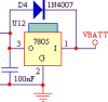
I've seen this in a few schematics, but not all. I do like to employ a diode inline with external power but I would like to know what the purpose of a diode across a regulator is.
it is meant to protect the transistors inside the regulator when it is being used in a high capacitance circuit
for example, lets say you have a huge output capacitor for some reason, and then your Vsup disappears for some reason (crowbared) - now the output side if the reg is at a higher potential than the input side, so current will want to flow from the output cap, through the reg, reverse biased ... the datasheet explains how to calculate wether or not you need that diode, as the reg have some built in protection.
so, with the diode there, if the output somehow reaches a higher potential than the input, the diode becomes forward biased and conducts the excess voltage safely around the reg.
Well we know he did not mirror it for a PCB my mistake because the text is still correct.
I stared at it. I went, OK power on the right. Do it that way. You can do it.
Only after I knew what the diode was for.
So he took the schematic from people that drive on the wrong side of the road... Or draws backwards.
Hey I learned something as I have never used a diode to feed the power back to the regulator (never had a big cap on that side I guess). I have used diodes to keep the user from attaching the power backwards many times.. So it all worked out.
So, what side do they drive on in Australia, just wondering? In Canada, it is on the "RIGHT" side..
under normal circumstances, no current will be flowing through the diode at all ... since the input voltage will be of a higher potential than the output, the diode will be reverse biased.
if something happens to cause the input voltage to drop below the output will the diode will become forward biased, and then do its job, and provide an low resistance path for current to discharge from the circuit, rather than forcing its way backward through the regulator
I wonder if there is any benefit to using a high speed schottky barrier instead of a gp silicon in this application, or would that depend on the power levels involved?
I wonder if there is any benefit to using a high speed schottky barrier instead of a gp silicon in this application, or would that depend on the power levels involved?
No, there's no benefit, fast recovery diodes are only really required for switchmode power supplies, or supplies fed from line output stages. If you replace them with normal rectifiers you soon find out why! 8)
I've got a question. Why does the diode go from to the output to input? Couldn't you just have the diode in series with the output to block reverse current and drop more voltage than the regulator in this scenario?
Also, if the diode in the diagram allowed too much leakage current, couldn't that cause a positive feedback loop and potentially make the regulator loose stability?
If you put the diode on the output side is series with the load, it would drop 0.7 or more Volt and reduce the regulation.
The leakage current of the diode will go into the load so the output current of the reg will be that much less than it would be if the diode was not there, for example, if the load current was 20 mA and the leakage current was 1 mA then the reg output current would be 19 mA.
Assuming that the output current is >> than the leakage current, it should not cause any problems.
So with the diode backwards, the regulator will take all the voltage through it before the diode? I have never tried it, and will not try it. I do not use a diode there anyway. But I will remember that. Thanks.
A diode in series with the output will drop 1/2 volt which is not desirable, and the diode resistance will reduce the regulation.
Leakage in the diode will reduce the amount of current that the regulator has to supply to the load. There is no feedback and no harm to the circuit as long as the leakage does not exceed the load current.
This site uses cookies to help personalise content, tailor your experience and to keep you logged in if you register.
By continuing to use this site, you are consenting to our use of cookies.

")