This project uses a 12F508 (or 12F509) to read a keypad and send the results over RS232. It is most useful as an add-on to other pic projects that require some way to input numbers. This keypad acts the same way as your PC keyboard in that when a key is held down, it has the short delay before it repeats the key. Both the delay and repeat speed are settable in software just like your PC keyboard.
Many people will wonder what "2 key rollover" means. The best answer is with a little demonstration. Open your favourite text editor, hold down the "A" key and when it starts repeating press the "B" key. Even though 2 keys are now held down the keyboard sends the last key pressed. This is useful because many people will press the keys so fast that they inadvertently press two keys at once.
How does it work.
The Schematic,

The 12F508 only has 6 input/output (I/O) pins and we need 1 to send the serial data out which leaves only 5 left to read the keypad. The keypad has 4 rows and 3 columns which is too many for our little pic chip. The way we get around this problem is by using the same pins twice. You see the three resistors in the diagram, well they will make the three pic pins low by connecting them to ground. If we now make GP4 high the diode on row 1 will conduct and if any keys are pressed in row 1 then the corresponding pin GP0, GP1 or GP3 will also go high. We have successfully read row 1. We can repeat this with GP4 and read row 3.
Now comes the tricky part because the diodes on rows 0 and 2 are backward and so the only way to read those rows is by outputting a zero on GP4 and GP5 thus making the input pins low. But, wait a minute, they are already low due to those resistors and so we won't see any change. Luckily for us the pics have internal resistors that connect the (input) pins to the 5V line that we can turn on and off in software. These resistors have a value around 20k and so will overpower the 200k external ones and make the input pins 5V. So, with these internal resistors turned on we can make GP4 an output, set it low and any pins that are now low will indicate a key pressed on row 0. We can repeat this using GP5 to read row 2.
The board,

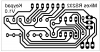
Closer,

The two sets of connectors are just for convenience, I added the second set to enable me to use it on a breadboard.
The finished article,

The code,
A video.
[embed]http://www.youtube.com/v/Q2xrVV9w-yE&hl=en&fs=1[/embed]
Note, this will not work with newer pic chips as they don't have the WPU on I/O 3.
<edit>Somethings I forgot,
The connections from left to right are GND, RS232 out and 5V.
The output is TTL and so can be connected straight to a pic RX pin without a MAX232 chip.
If you want an inverted signal to connect to a PC then uncomment the #define inverted line in the source.
You can change the repeat delay and repeat rate in the source.
</edit>
Mike.
Many people will wonder what "2 key rollover" means. The best answer is with a little demonstration. Open your favourite text editor, hold down the "A" key and when it starts repeating press the "B" key. Even though 2 keys are now held down the keyboard sends the last key pressed. This is useful because many people will press the keys so fast that they inadvertently press two keys at once.
How does it work.
The Schematic,
The 12F508 only has 6 input/output (I/O) pins and we need 1 to send the serial data out which leaves only 5 left to read the keypad. The keypad has 4 rows and 3 columns which is too many for our little pic chip. The way we get around this problem is by using the same pins twice. You see the three resistors in the diagram, well they will make the three pic pins low by connecting them to ground. If we now make GP4 high the diode on row 1 will conduct and if any keys are pressed in row 1 then the corresponding pin GP0, GP1 or GP3 will also go high. We have successfully read row 1. We can repeat this with GP4 and read row 3.
Now comes the tricky part because the diodes on rows 0 and 2 are backward and so the only way to read those rows is by outputting a zero on GP4 and GP5 thus making the input pins low. But, wait a minute, they are already low due to those resistors and so we won't see any change. Luckily for us the pics have internal resistors that connect the (input) pins to the 5V line that we can turn on and off in software. These resistors have a value around 20k and so will overpower the 200k external ones and make the input pins 5V. So, with these internal resistors turned on we can make GP4 an output, set it low and any pins that are now low will indicate a key pressed on row 0. We can repeat this using GP5 to read row 2.
The board,
Closer,
The two sets of connectors are just for convenience, I added the second set to enable me to use it on a breadboard.
The finished article,
The code,
Code:
;*******************************************************************
;		Title	12F509 RS232 KeyPad
;		Author	Mike Webb
;		Date 	12th January 2009
;		Version	1.0
;*******************************************************************
;
	processor	12F509

	include	"p12f509.inc"

	errorlevel	-302
	radix	dec

	__CONFIG   _MCLRE_OFF & _CP_OFF & _WDT_OFF & _IntRC_OSC

;uncomment the following line to invert the RS232 signal.
;when inverted it can connect straight to a PC without a MAX232

;#define		Inverted

#define		GPIO0	0
#define		GPIO1	1
#define		GPIO2	2
#define		GPIO3	3
#define		GPIO4	4
#define		GPIO5	5

#define		b_GPIO0	GPIO,0
#define		b_GPIO1	GPIO,1
#define		b_GPIO2	GPIO,2
#define		b_GPIO3	GPIO,3
#define		b_GPIO4	GPIO,4
#define		b_GPIO5	GPIO,5


#define		RS232	2
#define		b_RS232Out GPIO,RS232

		cblock	07h
OutByte
Temp
Count
Key0
Key1
Old0
Old1
Edge0
Edge1
KeyCount
		endc

KeyDelay	equ	35	;delay in 100th second until repeat kicks in
KeyRepeat	equ	10	;delay between repeated keys


		org     0h

;********************************************************************
;	4 meg clock = 1.0 meg instructions


		org     0h
		movwf	OSCCAL		;write calibration value

start		movlw	0
		OPTION
	#ifdef	Inverted
		bcf	b_RS232Out	;ensure RS232 is high
	#else
		bsf	b_RS232Out	;ensure RS232 is high
	#endif
		movlw	b'11111111'-(1<<RS232)
		TRIS	GPIO		;all input except RS232 output


		call	Wait100th
		call	Wait100th

Loop		Call	Wait100th	;needed for timing and debounce
		movfw	Key0
		movwf	Old0		;keep copy of previous keys
		movfw	Key1
		movwf	Old1
		call	ReadKeys	;read the key matrix into Key0 and Key1
		movfw	Key0
		iorwf	Key1,W		;any key pressed
		btfsc	STATUS,Z
		goto	Loop
		movfw	Key0		;get key state
		xorwf	Old0,W		;keep changed bits (pressed and released)
		andwf	Key0,W		;keep only new presses
		btfss	STATUS,Z
		goto	NewKeyDown
		movfw	Key1
		xorwf	Old1,W
		andwf	Key1,W
		btfsc	STATUS,Z
		goto	KeySame
NewKeyDown	movlw	KeyDelay	;start key delay
		movwf	KeyCount
		movfw	Key0		;edge = (key^old)&key
		xorwf	Old0,W
		andwf	Key0,W
		movwf	Edge0		;edges contains a 1 for each new key press
		movfw	Key1
		xorwf	Old1,W
		andwf	Key1,W
		movwf	Edge1
		goto	HaveKey
KeySame		decfsz	KeyCount,F	;key delay
		goto	Loop
		movlw	KeyDelay	;if KeyDelay is zero
		iorlw	0		;then no repeat allowed
		btfsc	STATUS,Z
		goto	Loop
		movlw	KeyRepeat
		movwf	KeyCount
HaveKey
;	having got to here then a key is pressed for the first time
;	or the repeat time is up and so it needs repeating.
;	Edge0 or Edge1 contain the key pressed.

		movfw	Edge0		;does edge0 have a bit set
		btfsc	STATUS,Z
		goto	IsEdge1		;no so must be edge1
		movwf	Temp
		movlw	255		;set count to -1
		goto	CountBits
IsEdge1		movfw	Edge1		;move edge1
		movwf	Temp		;into temp and
		movlw	7		;count to 7
CountBits	movwf	Count
		bsf	STATUS,C	;ensure it can't get stuck in loop
CountBitsL	incf	Count,F		;increment counter
		rrf	Temp,F		;until we find a set bit
		btfss	STATUS,C
		goto	CountBitsL
		movfw	Count		;W=key number 0-15
		Call	Bit2Key		;convert to key character
		call	Send		;send key via RS232
		goto	Loop


ReadKeys	movlw	0<<NOT_GPPU		;   WPUs ON
		OPTION
		movlw	b'11111111'-(1<<GPIO5)-(1<<RS232)
		tris	GPIO			;make I/O 5 output
		bcf	b_GPIO5			;and make it low
		call	BitDelay		;avoid RMW
		clrf	Key0			;will hold key state
		btfss	b_GPIO0			;if I/O 0 low then key pressed
		bsf	Key0,0			;so set the bit
		btfss	b_GPIO1			;repeat
		bsf	Key0,1			;for
		btfss	b_GPIO3			;other
		bsf	Key0,2			;keys
		movlw	b'11111111'-(1<<GPIO4)-(1<<RS232)
		tris	GPIO			;make I/O 4 output
		bcf	b_GPIO4			;and make it low
		Call	BitDelay
		btfss	b_GPIO0			;read next row
		bsf	Key0,4
		btfss	b_GPIO1
		bsf	Key0,5
		btfss	b_GPIO3
		bsf	Key0,6
		movlw	1<<NOT_GPPU		;WPUs OFF
		OPTION
		movlw	b'11111111'-(1<<GPIO5)-(1<<RS232)
		tris	GPIO			;make I/O 5 output
		bsf	b_GPIO5			;and make it high
		call	BitDelay
		clrf	Key1
		btfsc	b_GPIO0			;I/O 0 will be pulled low by
		bsf	Key1,0			;220k resistors unless key pressed
		btfsc	b_GPIO1
		bsf	Key1,1			;same for rest of row
		btfsc	b_GPIO3
		bsf	Key1,2
		movlw	b'11111111'-(1<<GPIO4)-(1<<RS232)
		tris	GPIO			;make I/O 4 output
		bsf	b_GPIO4			;and high
		call	BitDelay
		btfsc	b_GPIO0
		bsf	Key1,4			;read next row
		btfsc	b_GPIO1
		bsf	Key1,5
		btfsc	b_GPIO3
		bsf	Key1,6
		retlw	0

Bit2Key		andlw	15
KeyTable	addwf	PCL,F
		retlw	'7'
		retlw	'8'
		retlw	'9'
		retlw	'x'
		retlw	'1'
		retlw	'2'
		retlw	'3'
		retlw	'x'
		retlw	'*'
		retlw	'0'
		retlw	'#'
		retlw	'x'
		retlw	'4'
		retlw	'5'
		retlw	'6'
		retlw	'x'

	#ifdef	Inverted

Send		movwf	OutByte
		bsf	b_RS232Out
		call	BitDelay
		bsf	STATUS,C
SendLoop	rrf	OutByte,F
		movfw	OutByte
		btfsc	STATUS,Z
		goto	EndTransmit
		bsf	b_RS232Out
		btfsc	STATUS,C
		bcf	b_RS232Out
		call	BitDelay
		bcf	STATUS,C
		goto	SendLoop
EndTransmit	bcf	b_RS232Out
		call	BitDelay
		call	BitDelay
		retlw	0

	#else

Send		movwf	OutByte
		bcf	b_RS232Out
		call	BitDelay
		bsf	STATUS,C
SendLoop	rrf	OutByte,F
		movfw	OutByte
		btfsc	STATUS,Z
		goto	EndTransmit
		bcf	b_RS232Out
		btfsc	STATUS,C
		bsf	b_RS232Out
		call	BitDelay
		bcf	STATUS,C
		goto	SendLoop
EndTransmit	bsf	b_RS232Out
		call	BitDelay
		call	BitDelay
		retlw	0

	#endif


; at 1 meg instructions and 2400 baud
; delay is 1,000,000/2400 = 416 cc
; the calling loop and the call/return = 13
; therefore delay needs to be 403 cycles

; to change to 9600 baud
; delay needs to be 104 - 13 = 91
; which would be (3*30)-1 = 89 + 2 = 91

BitDelay	movlw	30	;134	change back to 134 for 2400 baud
		movwf	Temp
DelayLoop	decfsz	Temp,F;		(3*134)-1 = 401 + 2 = 403
		goto	DelayLoop
		retlw	0

Wait100th	clrf	Count
		movlw	13
		movwf	Temp
Delay100L	decfsz	Count,F;	(256*3)-1 = 767
		goto	Delay100L
		decfsz	Temp,F;		(13*(767+3))-1 = 10009 + 3 = 10012
		goto	Delay100L
		retlw	0

		END
A video.
[embed]http://www.youtube.com/v/Q2xrVV9w-yE&hl=en&fs=1[/embed]
Note, this will not work with newer pic chips as they don't have the WPU on I/O 3.
<edit>Somethings I forgot,
The connections from left to right are GND, RS232 out and 5V.
The output is TTL and so can be connected straight to a pic RX pin without a MAX232 chip.
If you want an inverted signal to connect to a PC then uncomment the #define inverted line in the source.
You can change the repeat delay and repeat rate in the source.
</edit>
Mike.
Attachments
Last edited:
")
