Continue to Site

Welcome to our site!

Electro Tech is an online community (with over 170,000 members) who enjoy talking about and building electronic circuits, projects and gadgets. To participate you need to register. Registration is free. Click here to register now.

  • Welcome to our site! Electro Tech is an online community (with over 170,000 members) who enjoy talking about and building electronic circuits, projects and gadgets. To participate you need to register. Registration is free. Click here to register now.

Rpm Counting

Status
Not open for further replies.
Nigel

Could you please draw me the sheme like you think it should work??

Today i have taken the sensor to the bosch car service.
And i informed about a tv repair man but he wasn't there.

At the bosch car service they had a old TV digital scope thing looks like it was just a computer.

Anyway armed with the sensor and a Iron Bolt, i went to the place.

The first problem i face is that its difficult to simulate the situation

But when i let the bolt touch the magnet and then i pull it fast away from the sensor, the scope response with a 1,1volts peak..

But i bet that like the situ now is mounted (there is for example more distance between the sensor and the splines??) also the speed wich i turn the wheel (the other half does that part of the job) wont be enough..

anyway it wouldn't be interesting either to be able to measure the hand turning speed.

lets say that the scale i want = 1Km/h then safety factor etc..

Lets make it 0,7Km/h...

when turning by hand means that i need to displace 2,7mtrs per second...

Thats 1,5 Rpm/second.. i never can test at that wheel speed (by hand)

Sow i don't know good what to do..

Anyway my feeling of 0,25volts wasn't to bad, when i tried hard with some splines like axle i could get that voltage.

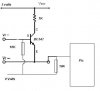
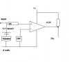
Conclusion: If you make me a transistor scheme wich can do that
(trigger 1 micro pin, with 0,25volts input) i'm just gona make that mount it and test it with the car on the road...

or maybe with some drill, but the problem is the revs / second....

Tks
 
Is there some reason you don't want to use an opamp?, they make it far simpler.

But here are the three standard transistor modes, I would suggest the left one (common emitter), add coupling capacitors on the input and output, and one across the emitter resistor to increase gain (if needed).
 

Attachments

  • transistors_615.gif
    transistors_615.gif
    5.3 KB · Views: 291
Something like this???

Nigel i have no idea how to do it, i'm still learning you know.

Found this part of emitter common have adapted it a bit..

What do you think??

From Vr+ to ground (o volts) i think i need to bult in a 100ohm resistor in series with a 5.1v zener when the voltage generated by the Vr sensor is higher the zener will keep the base voltage low right??

Regards,

Tks
 

Attachments

  • example_197.jpg
    example_197.jpg
    10.8 KB · Views: 290
the only reason i don't want to use one is i don't have one

If you think the radio man should have one model wich is commonly used
or maybe i could look in some old radio's i have over here...

if i untherstand it right: there is now 5volt applied to the circuit right??

Tks
 
Re: the only reason i don't want to use one is i don't have

TKS said:
If you think the radio man should have one model wich is commonly used
or maybe i could look in some old radio's i have over here...

if i untherstand it right: there is now 5volt applied to the circuit right??

That's in common collector (again!), and gives no voltage gain. It's also pretty doubtful it would work as it's not connected correctly.
 
Ok

i built that circuit earlier then you putted yours on the forum.

Anyway, will try to adapt yours to work with it.

altough i have no idea where to hookup the 5volts from the suplly or
the values of the resistors...

If you know of a opamp wich is many times used in grundig devices i will get a try to have one..

Tks
 
Re: Ok

TKS said:
i built that circuit earlier then you putted yours on the forum.

Anyway, will try to adapt yours to work with it.

altough i have no idea where to hookup the 5volts from the suplly or
the values of the resistors...

The +ve supply goes to the top, and the 0V to the bottom, it's pretty standard. You would need to work out the resistor values, which is why I suggested an opamp is easier.

If you know of a opamp wich is many times used in grundig devices i will get a try to have one..

Grundig have used various opamps, I salvaged a load of TL072 types from old Grundig VCR's years ago.
 
ok

tomorrow i think i will have a opamp,

hope you can (still will) help me when i have one

i have given the reference numbers of grundig and the one in the very first post.

The guy doesn't have any components like this on stock.
He lives in the big city (40miles) and travels daily sow i think
he calls the best shop over there and just let them put his order in a pub.

When goes for a drink they give him the order.

Its common to do suchs things over here..

Cheers and take some beer on our partnership :D ;)

thanxs nigel thanxs.
 
Sorry to jump in like that but I think you buy the wrong component...
I didn't read the complete four pages but checked most of the schematics.

TKS, if you have money to buy a scope I think you may consider buying a Hall effect switch, less than 3.00€.
Every time a magnet passes along the switch his output will go high (or low) while it's low (or high) with no magnet before it.

Check application note 27701B from Allegro "Hall effect IC applications guide". You will find lots a schematics, mechanical setups and more ...

You can buy these switches on line from www.conrad.de "HALL-SENSOR TLE4935L/Q67006-A9112" best.-Nr. 153775-62 is a usable part.

By the way, you can also buy a scop there :wink:

Hope this help... ...
 

Attachments

  • an27701_hallsensorapplicationguide.pdf
    791.7 KB · Views: 317
thanxs!

no problem more smiles more fun.

The only thing is that i wanted to use the abs hub/abs sensor of the front wheel.

I only need to ¨see¨ a bigger signal with an amplifier (op amp) i can just do this.

dunno wy but in cars they always use this kind of sensor.

The hall one is used by the ignition, the vr type is used for Tach(Cilinder one position), abs sensors etc..

Tks
 
GREAT NEWS!

Hot from the printer

i have got the TL072 Just like you ordered Nigel..

Now i need help with the next step..

i have ordered and recieved all the parts just like in the schematic wich uses the Mc34xxx..


Can you draw the scheme up for me nigel please??

Regards,

Tks
 
Nigel

Can you help a bit with the sheme??

I already have soldered the Chip to the pcb and hooked it up to the pic,Gnd,Vdd

But when looking at the + entrance and the - entrance... dunno what to do...

Do i just hookup the Sensor to the - and make a small Variable power supply for the + or what??

Tks
 
Nigel

I still wanted to put the zener there (with the 100ohm) for when the voltage starts riseing! they say the sensor could make up to 50volts!!

Wich resistances would be smart to put a pot on it???

I think the 100K bridge..??

And one of the 2 10K?

Thanxs! will build it straight away

Tks
 
Re: Nigel

TKS said:
I still wanted to put the zener there (with the 100ohm) for when the voltage starts riseing! they say the sensor could make up to 50volts!!

It shouldn't be a problem!.

Wich resistances would be smart to put a pot on it???

I think the 100K bridge..??

And one of the 2 10K?

The 100K could be variable, but NOT the 2x10k, they simply generate a split supply for the opamp.
 
no

i only wanted to do 1 of the 2

sow i could adjust the voltage on the pin.
(its the compare voltage right??)

Wy do you add the first cap after the sensor ??

i always thought it would takeaway voltage...

will it equalout more the signal??

Tks
 
NIgel

is it needed to pull up or pull down the pic pin??

I cant do it right?? the voltage will go to the input using the 100K trimmer right??

TKs
 
Re: no

TKS said:
i only wanted to do 1 of the 2

sow i could adjust the voltage on the pin.
(its the compare voltage right??)

NO! - it's NOT a comparator, it's an AC inverting amplifier, the two resistors are used to generate a split supply for the opamp.

Wy do you add the first cap after the sensor ??

If you don't it shorts out the DC input to the opamp to negative, forcing the output to swing hard to the positive rail.

i always thought it would takeaway voltage...

The output of the sensor is an AC signal, the capacitor is there to pass AC and block DC.

will it equalout more the signal??

No, it just passes the AC and allows the DC conditions to remain correct.

It's a very basic circuit, a simple inverting amplifier using a single power rail.
 
Comparator circuit

Nigel i installed the comparator jus tlike you said.

Only with one 10K pot in place (to 5volts) and one 100K one.. (hysteris??)

With those 2 i could adjust the signal.
But the problem is that the comparator voltage is to often 0,7 to 0,9
and then the pic's pin state changes very often and that generates wrong pulses...

I have made a program wich could make a graph about the pulses recieved. Always the best adjustment i could made.

I saw that the pulses recieved where to doubtfull sow when i give a good swing at the wheel it creates an mountain landschape with the peaks
going lower when reaching the lower speed.

When almost 0 rpm we get the doubtfull signal and it then generates a huge peak wich is impossible to his speed.
the value i recieved whas near 120pulses within 125ms.

Then i places a cap between the pic pin and the 0voltage. (1uF).
(i placed it after the other cap).

Then the values where allot better and you could see on the graph that the speed was getting lower and lower... but again when it reached alomost 0rpm it generates a huge spike....(200pulses)

the overall values was 100..pulses (sow 20 lower).

To eliminate the huge spike a changed the 1uf to 10uf but then it was unable to produce the nise moutain wich goes lower..(signal gets worse)...

I also tried with a 110K pulldown resistor and when i add that one i need to change both the pots (a lot of power is lost???).

Then the biggest surprise with the wheel from the ground i started the engine...

Then it looked like the engine noise was getting onto my circuit!!
when not turning the wheel i recieved some spikes, i could eliminate them a lot by adjusting both pots but it then it won't recieve well the signals


Question is it possible to connect the output of the TL to a NPN?
and add a pullup / pulldown with the perfect values for any voltage on the base higher then 0,6???

I need to take away the doubts from the pic/signal???

Hope you can give me some ideas

Tks
 
Status
Not open for further replies.

Latest threads

Back
Top