Continue to Site

Welcome to our site!

Electro Tech is an online community (with over 170,000 members) who enjoy talking about and building electronic circuits, projects and gadgets. To participate you need to register. Registration is free. Click here to register now.

  • Welcome to our site! Electro Tech is an online community (with over 170,000 members) who enjoy talking about and building electronic circuits, projects and gadgets. To participate you need to register. Registration is free. Click here to register now.

Rotory Encoder Woes

Status
Not open for further replies.
I prefer polling, especially if there is any chance of bounce or an indeterminate position (optical at 50%). I've looked at your code and can't see any reason for the double increment, as you say, it makes no sense. If you work out why it's happening please report back as I'm very curious.

Mike.
 
I did get it to work now, but it's strange the way it 'forces' a count of 2 increments instead of just 1. I've never seen anything so illogical before. Anything i do to make it count only 1 does not work, it becomes erratic.
... I cant explain yet why it insists on counting by 2..

You explained it yourself before. You said that the signals are always either 'both high' or 'both low'. In order this to happen the signals need to go through two transitions. You are counting both of those transitions when you move the encoder 'one click'.

Try counting transitions on one line only:

dir = 0;
if(sum == 0b1101 || sum == 0b0010) dir = 1;
if(sum == 0b0111 || sum == 0b1000) dir = -1;
count = count+dir;
 
Last edited:
You explained it yourself before. You said that the signals are always either 'both high' or 'both low'. In order this to happen the signals need to go through two transitions. You are counting both of those transitions when you move the encoder 'one click'.

Try detecting transitions on one line only:
In code:
if(sum ==0b1101 || sum ==0b0010) dir=1;
if(sum ==0b0111 || sum ==0b1000) dir=-1;

.. Or just disable interrupts from one of the data lines.

This is a very good point. An encoder that is specified as, say, 10 pulses per revolution (PPR) will in fact have 4 times as many state transitions in one full revolution (40 transitions for the 10 PPR encoder, when you count both the positive and negative transitions of both encoder outputs). In the project that I have been working on, the 4096 PPR encoder produces 16384 transitions. Since the code actually counts the transitions, it must then divide the result by 4 to give the expected 0-4096 count.
 
You explained it yourself before. You said that the signals are always either 'both high' or 'both low'. In order this to happen the signals need to go through two transitions. You are counting both of those transitions when you move the encoder 'one click'.

Try counting transitions on one line only:

dir = 0;
if(sum == 0b1101 || sum == 0b0010) dir = 1;
if(sum == 0b0111 || sum == 0b1000) dir = -1;
count = count+dir;

Hi there MisterT,

As soon as i saw your code i knew there was something just right about it :)
It turns out that the 'web' code library was looking for too many state transitions. It was looking for 3 kinds of transitions rather than just two kinds.
The explanation is that the encoder goes through 3 static state changes but we must only detect 2 out of those three dynamically. That's why only counting on every other interrupt did not work either (which divides by 2 if there were four interrupts), because then it is out of sync with the required even number of interrupts per click.

I have drawn out a diagram of the encoder waveshapes and detect codes for anyone else interested in this too, but for a simple explanation the static codes (which the program was detecting for some reason) are:
00 to 10 to 11, and 11 to 01 to 00,
but we must only detect:
10 to 11 and 01 to 00
which are the ones that would be 'seen' by the interrupt routine because it only looks at the codes AFTER a single (dynamic) state change.

I plugged it in (slightly different just because of the variables i am using now) and it worked right off the bat:

if((sum == 0b0100) || (sum == 0b1011))
{
dig+=1;
}

if((sum == 0b1110) || (sum == 0b0001))
{
dig-=1;
}

'dig' is the digit being incremented or decremented at the time, and there is range checking later to make sure the digit can not go beyond the limit for that digit (either 0 to 9, or 0 to 4).

Thanks a bunch :)

I included the waveshapes and code output diagram in the attachment.
We can see that Click 1 and Click 2 in the clockwise direction produce dynamic changes that are different, but allowing the previous interrupt code to allow another count is what causes too many counts. To reverse direction just reverse the order of the waveforms and codes, reading them right to left instead of left to right. "A pulses" and "B pulses" refer to interrupts on change being detected on those two pins respectively.
 

Attachments

  • RotaryEncoders_Interrupts-2.gif
    RotaryEncoders_Interrupts-2.gif
    20.1 KB · Views: 307
Last edited:
****** VERY INTERESTING DEVELOPMENT *******


I just received the new encoders today, and it was easy to disconnect the 'old' one and connect one of the new ones by just unplugging the test jumpers and plugging in the new one.
To my dismay, the friggin' counter started counting by 2's again, and i rarely find a need to use double exclamation points but now is the time: !!

So time to back up one square. I plugged it into the two LED tester (to be able to see the pattern clearly as the encoder shaft is rotated) and wow, it's a different pattern!

Old pattern: 00 01 11 10 00 (and you can read that from right to left for opposite rotation)
New pattern: 00 01 10 00 (and you can read that from right to left same reason)

So the difference is with the previous encoder it had an intermediate state of both contacts 'on', while the new encoder has no such state, but does have the other states.

Conclusion: The two types of encoders will have to be done differently unless a common set of code can be found that will work for both.

Now i can see why there is so much difference in codes for these things on the web, and some people complain that the code does not work, and that is probably because it was made for a different encoder. As i said, if i used the old code (that works with the older encoder) for the new encoder it AGAIN will increment by 2 for every click even though it works fine for the old one.

For your convenient reference:
The older one is labeled "Keyes" and also has a capitol "V" on it near a mounting hole.
The newer one is not labeled at all, except for the capitol "V" on it near a mounting hole.
The newer one also has screw threads on the shaft mount like a potentiometer has, while the older one (Keyes) does not have threads.
The older one encoder body itself is colored green, while the newer one body is colored blue.
There are minor differences in the construction of the body besides the threads for the new one.
The shaft rotation direction relative to the CLK and DT terminals appears to be reversed for the new encoder, but because the code is not right yet i will have to double check this later.

Common to both:
They both have a flatted shaft.
They both have: CLK, DT, SW, +, GND in that order.
They both have black colored boards that look the same (except for the label "Keyes").
They both have two SMD 10k resistors (for the encoder bits) mounted and missing one 10k resistor (for the push switch contacts).

Interestingly, before i worked with either of these i expected to see this new pattern not the old one. I was surprised that there was an in between state like that. But in any case, i have to find the new pattern detection now although that should not be too hard to do having the older code that works now. A slight mod should do it, and i will also look for a common code to do both without having to change anything.

If you have any ideas or more information about this or any other encoders, please list here in this thread. There could be other pattern encoders out there too (2 bit types that is as i am sure the multi bit type will be vastly different and require a very different code write).

It is lucky that i found this out now rather than later.
 
Mr Al, I like your timing diagram that you posted. Did you make that, or was it part of a data sheet or something? If you made it, what did you use to make it? Just curious cause I liked it:)
 
Hi Mike,

Oh thanks, but i am happy you asked that because i should have made it more clear what that each thing stood for.

First, for the actual timing diagram with waveforms, i found the waveforms on the web already drawn but it was just a little sloppy so you could not tell what happened during each click, which we should be able to tell. So i simply copied the waveforms and then redrew everything else, like the timing lines (blue) so that we could tell what happened for each click, and since the whole pattern for the encoder i was working with encompassed a span of not just one click but two clicks (which i found odd) i had to show what happened for each of the two clicks. I did not feel it was too important to show both directions though because the reader could just read across the page in the opposite direction, but i guess it would be more complete to draw that too.

The more simplified way i have found to show this though is with 1's and 0's (ones and zeros). The first bit is the A terminal (or CLK) and the second bit is the B terminal (or DT). So two bits drawn as "10" mean A was high and B was low, and groups of pairs show the entire sequence of internal switch closures and non closures. For example:
00 10 01 11

would be read left to right, and:
the first pair means A was low and B was low,
the second pair means A was high and B was low,
the third pair means A was low and B was high,
and the last pair means A was high and B was high also.
The actual direction of rotation was not given, but could be assumed to be clockwise, but the pairs one single click produces is different for each encoder. Statically the first encoder did:
00 10 01 11
for one click, then:
11 10 01 00
for the next click (the two clicks generate different pattern).
The second encoder did:
00 10 01 00
for one click, then:
00 10 01 00
for the next click (both clicks the same pattern).
Dynamically we simply skip the first pair for any single click assuming two on-change interrupts one for each pin A and B (which we might be able to improve upon).

The simplest way to test (but reverses the polarity of each bit) is to connect the GND pin to a 1k resistor, and the other end of the 1k goes to +5v (yes that's +5v not ground). Using two LED's, one LED anode goes to A and the other LED anode goes to B, and both LED cathodes go to ground.
Now when the encoder is turned very slowly, each state becomes clearly visible by observing the LED's as they light up and go out. If an LED lights up, the switch is closed, and if an LED does not light up, the switch is open.
I have represented a switch closed with a '1' and an open with a '0'. This will be backwards from the typical use because the GND terminal is connected to ground and so when the switch is closed the digital input pin will read a zero '0', so if you like you can flip the 1's and 0's.
 
Last edited:
Hello again,


The new code came out even simpler.

For use with blue encoder with one click static rotation patterns:
00 10 01 00 anticlockwise
00 01 10 00 clockwise


volatile byte LastEncoded=0;

void ISRa(void)
{
delayMicroseconds(20000);

int MSB = digitalRead(2); //MSB = most significant bit, int on change pin #1
int LSB = digitalRead(3); //LSB = least significant bit int on change pin #2

int encoded = (MSB << 1) |LSB; //converting the 2 pin value to single number
int sum = (LastEncoded << 2) | encoded; //adding it to the previous encoded value

if(sum == 0b1000)
{
dig+=1;
}

if(sum == 0b0100)
{
dig-=1;
}

LastEncoded=encoded;

}
 
Just to be clear, are you now getting this?

00 01 10 00 01 10 00 01 10 00 01 10 00 clockwise

Are you only getting 3 different states instead of 4, quadrature?
 
Hi,

Yes, that's right, and let me be more clear about this.

First, when the rotary shaft is not being turned it will always result in both switches open, which i represent with the code 00 (two zeros) because both A and B switches are open. I represent a switch closed with a '1', so that code 11 means both switches are closed, which means they connect to ground, so we get a zero not a 1, but no big deal.

When it is turned very carefully 1/3 of a click, the code changes to 10, then turned another 1/3 of a click it changes to 01, then when it makes the full click and comes to rest it reads 00 again. So the entire sequence of one click is 00 10 01 00, but since it rests at 00 the first 00 doesnt really count, that's just the starting state, so we see changes as 10 01 00 only, until the next clock.

The older encoder (green body) if starting at code 00 would go as:
00 10 01 11
for the first click, then
11 10 01 00
for the next click.
So it took two clicks to get the entire sequence of possible codes, but for each click we still only got 3 changes. If it started on 00 then it would end on 11, but if it started on 11 then it would end on 00.
 
So are you using this encoder to tune your DDS chip?
 
When I used optical encoders in the late 70's I was tracking a linear probe on a spool aircraft cable spool drive with 1mm resolution up to 10m/s which is 10kHz. No problems and that left lots of margin.
Stopless encoder rotary controls used in DSO's etc may not be as fast but pulse rate depends on number of pulses per rev and rotation speed.
My guess is you would like to have 10 clicks in about 90 deg. or about 40 clicks per rev. for decimal selection , or simply use a BCD encoded rotary switch.
The options now are; 32, 64, 100, 128, & 256 pulses per rev.

These have a 200ns rise/fall time, from an optical quadrature encoder.

You can design it directly in hardware with a decimal up/down counter and read the result in parallel then use 3 switches. Left digit, select and right digit or use firmware to shift the digit from MSB to LSB after each select with only one switch using absolute or scientific notation and as many digits as you need.

Then another switch to load the resulting value or a longer duration on the select switch selected by firmware.

These are expensive but feel good. https://www.digikey.com/product-detail/en/EM14A0D-C24-L032N/EM14A0D-C24-L032N-ND/954402

I would be inclined to modify an optical mouse with a really good plastic wheel and use that for the interface. and use the twin optical detectors included and breakout the pulse forward and reverse into an Up;Down counter for parallel reading.... or use the Mouse/joystick port or the USB port.....

THe logic can reset the counter after read port is done and internally shift the digit towards Least significant digit. Then you can use a button mouse for left/right/ select and combinations for more features like increment frequency and step size.
 
Last edited:
So are you using this encoder to tune your DDS chip?


Hi,

Well, that is one of the intended end application uses yes. These encoders can be used for a lot of different user adjustment features on any project as well as detecting slowly turning motor shafts. Right now i am looking into some other issues with some other things though.

The encoders also have a built in push button, so if you push the shaft you get a momentary switch closure on the third pin just like a regular momentary push switch. This will probably be used to select the digit to be incremented/decremented. The rotation will change the selected digit from 0 to 9 in the display to read out the 9 digit frequency (7 digits to the left of the decimal point and 2 digits to the right). The number is then read and converted into the control bytes and sent to the DDS frequency generator chip.
 
When I used optical encoders in the late 70's I was tracking a linear probe on a spool aircraft cable spool drive with 1mm resolution up to 10m/s which is 10kHz. No problems and that left lots of margin.
Stopless encoder rotary controls used in DSO's etc may not be as fast but pulse rate depends on number of pulses per rev and rotation speed.
My guess is you would like to have 10 clicks in about 90 deg. or about 40 clicks per rev. for decimal selection , or simply use a BCD encoded rotary switch.
The options now are; 32, 64, 100, 128, & 256 pulses per rev.

These have a 200ns rise/fall time, from an optical quadrature encoder.

You can design it directly in hardware with a decimal up/down counter and read the result in parallel then use 3 switches. Left digit, select and right digit or use firmware to shift the digit from MSB to LSB after each select with only one switch using absolute or scientific notation and as many digits as you need.

Then another switch to load the resulting value or a longer duration on the select switch selected by firmware.

These are expensive but feel good. https://www.digikey.com/product-detail/en/EM14A0D-C24-L032N/EM14A0D-C24-L032N-ND/954402

I would be inclined to modify an optical mouse with a really good plastic wheel and use that for the interface. and use the twin optical detectors included and breakout the pulse forward and reverse into an Up;Down counter for parallel reading.... or use the Mouse/joystick port or the USB port.....

THe logic can reset the counter after read port is done and internally shift the digit towards Least significant digit. Then you can use a button mouse for left/right/ select and combinations for more features like increment frequency and step size.

Hi,

These type of encoders are the cheap ones, 1 to 2 dollars USD. They have two switch contacts inside that make contact with the arm that rotates. The first one had 30 detents, the second one has 20 detents like the
Bourns PEC11L-4220F-S0015
The pattern looks the same as that one too, and the body is colored blue.


The 28USD one is really too expensive for a hand driven rotary encoder. It does not need to be that fast really. The one above does 60rpm which is probably plenty for a hand turned unit.
I did note they recommend 100 to 200us time constant filters however, one for each tap. But that may be when not using a microcontroller, which can do debouncing. The max bounce they state is 10ms, and 10ms seems to be a good value in the code.
The life is a little limited, about 100000 actuations min, so a better encoder would help there too.

I thought about modifying an old mouse, but i am not sure i want to be bothered with that. The wheel, after all, is an encoder that is designed for a life with a huge number of rotations. The regular 'ball' type also have two encoders just for that, so one mouse could yield three encoders. I have mostly laser type mice though, with only one wheel, and one of the wheels on one mouse is broken already that's why i got a new mouse :)
I might still look into this in the future, depending on what else i have to do concurrently and energy i have left after that :)
 
It takes a lot of turns to get from 1 KHz to 40 MHz. Are you skilled in the task?

John
 
Hi John,

Ha ha :)

It takes 40000 clicks (2000 rotations) to get from 1kHz to 40MHz, but it takes 40,000,000 clicks (2,000,000 rotations) to get from 1Hz to 40MHz. Luckily i have a rotationally jointed elbow so i can turn the shaft around and around a lot of times really fast :)

Ok really, the push button there is to change 'digits' first before rotating the encoder.
At power up, the least significant digit is selected out of all these digits:
00,000,000.00

and that is the one on the far right:
00,000,000.00

Turning the encoder one click results in:
00,000,000.01

Now pressing the button two times, then turning the encoder three clicks results in:
00,000,003.01

and now pressing the button again 7 times and turning the encoder one click results in:
10,000,003.01

I will probably change this however, so that the first digit to change is on the left and will be indicated as a blinking digit or underline:
_0,000,000.0

the next digit after one button press:
0_,000,000.00

and the next:
00,_00,000.00

and now we turn the encoder to set the 100's of kilohertz.

So the encoder never has to be clicked more than 10 times to set any given digit of 9 digits. Since it also goes down by clicking counter clockwise, we can get to '9' with one click too if that digit starts at zero '0'.

It's not hard to set this up in code once the encoder is being read properly, and converting to a set of control bytes isnt hard to do either as you know well.

What i havent looked at yet is how to use multiple encoders. What if we wanted a separate encoder for each digit? That would require 9 encoders but all of them would have to use the same 2 pins on the Atmel 328P chip i think. Maybe multiplexing of some type.
 
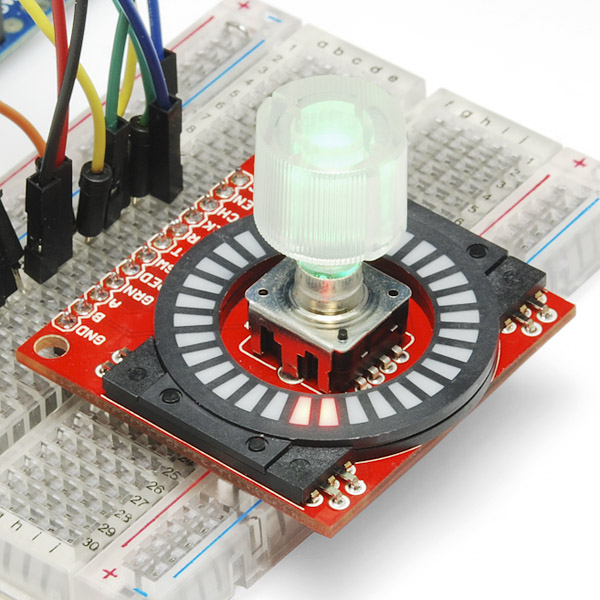
Something like this circular LED add on would make your project look cool :) If your into that sorta thing?
Action_Shot-01.jpg
 
In one of the later iterations of the VFO project using a DDS module ( See:VK5TM's stuff on the DDS modules), they used the speed of encoder rotation to determine the size of the encoder steps, much like some modern mice do. That adds a new dimension (time). A fast turn may increment by 10's of kHz, while a slow turn may only increment 10 Hz per revolution or so. Your proposed method does much the same thing, but I think users may be more accustomed to the mouse way.

John
That sounds like a good way to go. I like it.
 
Something like this circular LED add on would make your project look cool :) If your into that sorta thing?
Action_Shot-01.jpg


Hi,

Yes that is a nice display, for showing the rotation that is. That might be good when you have to show the user what the rotary knob is pointing too, like the usual number 1 to 10 for volume or something.

I guess you could say i am "totally" into stuff like that. And that is because i believe that the human person wants to use things that are very presentable and have a tint of artistic persuasion over things that are just plain functional.
I see more and more things coming out that may be focusing more on that aspect of product design. That really sells stuff.
 
Last edited:
Status
Not open for further replies.

Latest threads

Back
Top