Continue to Site

Welcome to our site!

Electro Tech is an online community (with over 170,000 members) who enjoy talking about and building electronic circuits, projects and gadgets. To participate you need to register. Registration is free. Click here to register now.

  • Welcome to our site! Electro Tech is an online community (with over 170,000 members) who enjoy talking about and building electronic circuits, projects and gadgets. To participate you need to register. Registration is free. Click here to register now.

Req: simple low drop constant current source

Status
Not open for further replies.

Dominique

New Member
Hello,

'cause it's my first post, a big hello to everyone here! :)
I hope you won't throw me out after my first silly questions!

I'm looking for a constant current source with a low voltage drop!

The application:
Power comes from a bike's dynamo. Voltage is AC at frequencies roughly between 30Hz and 100Hz.
Voltage can vary (at max.) between 4.2V (climbing a hill) and 7.5V (normally less, but depends on dynamo and frontlight's current draw).
The thing I want to power are two red LEDs in series, normally they are 2V each. They'll get between 10 and 20mA.
So now I need a supply with a very low drop-out, to get a satisfactory current even at 4,2V.

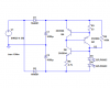
Also, I'd like it to be simple! The circuit on the image is not that bad, it gives me (trusting LTSPice) 4,4mA per Diode at 4.2V and 9,8mA at 7,5V.
It's not that bad, but I'd like the current difference between high and low volatge to be lower.

Also, I imagine to use that circuit 2 times, one for each AC leg. Ok, I'll probably add a capacitor in order to reduce the flickering, but I don't have much space. I'll decide on the caps when I see the circuit in action.

I'd be very glad for any suggestions!
Dominique
 

Attachments

  • constantcurrent.gif
    constantcurrent.gif
    7.9 KB · Views: 1,194
It sounds like your circuit would be suited to a switching voltage regulator. These basically provide a certain output voltage even when the input varies within some voltage range. they're called 'boost' regulators if the output voltage is always higher than the input, 'buck' if it's lower, or boost-buck if the output voltage is somewhere in the middle of the input voltage range. Depending on how you drive your LEDs you could probably use any of those configurations; in fact, if you are really set on a constant current source, you could use a boost regulator to increase the input voltage to drive your current source with a higher voltage so you didn't need to worry about dropout.
 
I agree that a switcher would be more efficient. Here is an idea that doesn't require one, but of course is not so efficient: (Save the code as "filename.asc" if you don't want to have to redraw the schematic.)
Code:
Version 4
SHEET 1 1120 724
WIRE 80 176 80 80
WIRE 80 336 80 256
WIRE 80 352 80 336
WIRE 240 80 80 80
WIRE 240 608 240 80
WIRE 320 80 240 80
WIRE 320 608 240 608
WIRE 464 80 384 80
WIRE 464 192 464 80
WIRE 464 336 80 336
WIRE 464 336 464 256
WIRE 464 432 464 336
WIRE 464 608 384 608
WIRE 464 608 464 496
WIRE 672 80 464 80
WIRE 672 160 672 80
WIRE 672 288 672 256
WIRE 672 352 672 288
WIRE 672 480 672 448
WIRE 672 608 464 608
WIRE 672 608 672 560
WIRE 848 288 672 288
WIRE 912 80 672 80
WIRE 912 112 912 80
WIRE 912 208 736 208
WIRE 912 208 912 192
WIRE 912 240 912 208
WIRE 912 368 912 336
WIRE 912 400 736 400
WIRE 912 400 912 368
WIRE 912 448 912 400
WIRE 912 608 672 608
WIRE 912 608 912 576
WIRE 976 368 912 368
WIRE 1040 80 912 80
WIRE 1040 224 1040 80
WIRE 1040 368 976 368
WIRE 1040 368 1040 304
FLAG 976 368 D2
FLAG 80 352 0
SYMBOL voltage 80 160 R0
WINDOW 123 0 0 Left 0
WINDOW 39 0 0 Left 0
SYMATTR InstName V1
SYMATTR Value SINE(0 4 30)
SYMBOL pnp 736 256 R180
SYMATTR InstName Q4
SYMATTR Value 2N3906
SYMBOL pnp 848 336 M180
SYMATTR InstName Q5
SYMATTR Value 2N3906
SYMBOL res 896 96 R0
SYMATTR InstName R3
SYMATTR Value 33
SYMBOL LED 896 448 R0
WINDOW 3 81 42 Left 0
SYMATTR InstName D3
SYMATTR Value QTLP690C
SYMATTR Description Diode
SYMATTR Type diode
SYMBOL LED 896 512 R0
WINDOW 3 82 41 Left 0
SYMATTR InstName D4
SYMATTR Value QTLP690C
SYMATTR Description Diode
SYMATTR Type diode
SYMBOL npn 736 352 M0
SYMATTR InstName Q6
SYMATTR Value 2N3904
SYMBOL res 656 464 R0
SYMATTR InstName R5
SYMATTR Value 4.7k
SYMBOL res 1024 208 R0
SYMATTR InstName R6
SYMATTR Value 100k
SYMBOL diode 320 96 R270
WINDOW 0 32 32 VTop 0
WINDOW 3 0 32 VBottom 0
SYMATTR InstName D1
SYMATTR Value 1N4001
SYMBOL polcap 448 192 R0
SYMATTR InstName C1
SYMATTR Value 1000µ
SYMBOL polcap 448 432 R0
SYMATTR InstName C2
SYMATTR Value 1000µ
SYMBOL diode 384 592 R90
WINDOW 0 0 32 VBottom 0
WINDOW 3 32 32 VTop 0
SYMATTR InstName D2
SYMATTR Value 1N4001
TEXT 70 432 Left 0 !.tran 100m
 

Attachments

  • led_current_source.png
    led_current_source.png
    11.3 KB · Views: 1,007
Here's simpler:
Run the AC into a full wave bridge, filter it to DC, and run each LED on a separate current source.

Each current source is a bipolar with a resistor in the emitter, bases tied together. and shunted to ground through a third transistor collector to ground.

The third transistor's base connects to one of the emitter resistors of the current driver transistors. One resistor to +V provides base drive and the LEDs are one in each collector of the CC transistors.

That should do it. Those CCs will saturate to under 1V if you use reasonably high gain/high current devices.
 
R.G. said:
Here's simpler:
Run the AC into a full wave bridge, filter it to DC, and run each LED on a separate current source.

Each current source is a bipolar with a resistor in the emitter, bases tied together. and shunted to ground through a third transistor collector to ground.

The third transistor's base connects to one of the emitter resistors of the current driver transistors. One resistor to +V provides base drive and the LEDs are one in each collector of the CC transistors.

That should do it. Those CCs will saturate to under 1V if you use reasonably high gain/high current devices.
It's a good idea. The FW bridge was my first thought too, but it won't put out full current at 4V peak. The double half-wave circuit has room to spare at 4V, and also draws less current (which probably isn't a big deal in this case).
A thousand pardons if this is not what you described.
 

Attachments

  • led_current_sources_waves.png
    led_current_sources_waves.png
    12.1 KB · Views: 760
  • led_current_sources_sch.png
    led_current_sources_sch.png
    14.7 KB · Views: 914
Yeah, that's the circuit I had in mind.

Maybe I'm reading his notes wrong. I was using 4.2Vrms in the sim, and it worked fine and dandy.

I went back and put in 2.97vrms/4.2V peak and got about 15ma on each LED. That may or may not be enough for the application. It pulled out of CC regulation for 20ma at about 4.7Vpk/3.3Vrms. But it was still about 15ma.

The real question here I think is what's the internal regulation of the source? If it's got a good low internal impedance, either way works - yours certainly and mine almost. If it's got say, 5 ohms internal impedance, my way sags to about 12ma and yours is just beginning to pull out of regulation. So I think the doubler is much more constant current.

It's a tradeoff between two additional diodes to make a bridge and one additional capacitor for the doubler, with better performance on the doubler. The FWB will be fine with 1000uF, so the caps can be the same size as well.
 
I think Ron H's idea of a 1/2 wave voltage doubler is great. Add a LM317L
Z (To-92, 100Ma) adjustable regulator with a 62 ohm resistor between the out terminal and the adjust terminal will create a 20 Ma constant current source. Connect the LED's series from the adj terminal and the - point of the voltage doubler output. The input of the regulator to the + of the voltage doubler. Less parts and simpler.
 
Quite simply, I think the idea of splitting the two LEDs into separate legs of the current source is brilliantly simple, and I smacked my forehead the moment I read it for not thinking of it myself! :lol:
 
hi,
unexpectedly I was away for two days, and now I'm very glad to come back and find your helpful answers. :) It's very late now (1:50 here in Germany), so I'll read it all tomorrow and I'll gladly try the proposed ideas!
Thanks already and see you soon!
Dominique
 
Hey,

I don't feel comfortable now: You've put your ideas in here, and Ron has even made those schematics and simulations (Wasn't there a saying: "A Schematic tells more than a 1000 words") :) and me, I didn't find the time to reply!
I thank you very much! And those are good ideas!
Unfortunately both circuits are less efficient than what I'm looking for. Mostly, the voltage will be 6V and therefor, I'd really like to use more than 2V (as in the "one LED per regulator" suggestion) of it. Of course, your suggestions are very good in case of low voltage, but I hoped for a solution with simply a lower voltage drop than my circuit.
I also tried a voltage doubler version with a reg1117: very simple, but it seemd to draw a lot of current from the voltage source!

Maybe I'll have to try the circuits for real now.
Whenever in the simulation I used capacitors to even out the DC, the currents were very high. Ok, that's normal, but when I made an average current out of it (after the caps were fully loaded of course) by view and by measuring, the average was way higher than expected and than in the version without caps! I don't remember exactly, but the loss was in the range of 1/3 or even 1/2, that's something I don't understand. Those standard capacitors don't waste that much energy, do they?

In addition, I'll look for a step-down regulator circuit, which hopefully regulates the current at the same time as being simple!

Thanks again,
Dominique
 
Dominique said:
In addition, I'll look for a step-down regulator circuit, which hopefully regulates the current at the same time as being simple!

The circuits above are already VERY simple, I doubt you would get anything that works anywhere near as well with less parts?.

To make it more efficient would probably require moving to switch-mode designs, greatly increasing the complexity - which probably isn't worth it for lighting a couple of LED's? - you wouldn't notice any change in the pedal power required!.
 
Status
Not open for further replies.

Latest threads

New Articles From Microcontroller Tips

Back
Top