Electro Tech is an online community (with over 170,000 members) who enjoy talking about and building electronic circuits, projects and gadgets. To participate you need to register. Registration is free. Click here to register now.
Welcome to our site! Electro Tech is an online community (with over 170,000 members) who enjoy talking about and building electronic circuits, projects and gadgets. To participate you need to register. Registration is free. Click here to register now.
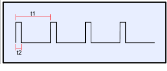
After removing them and measuring the signal between the gate and source pins , i see a clean square wave but it is always set at 25 % even though am increasing the output current .
I get a signal like this one .
I think my understanding of your question must be wrong. It appears to me that you have removed the IGBTs and are still getting an output otherwise how can you increase the output current. I do not see how the power supply can work with the IGBTs removed.
I think my understanding of your question must be wrong. It appears to me that you have removed the IGBTs and are still getting an output otherwise how can you increase the output current. I do not see how the power supply can work with the IGBTs removed.
I have been assuming that this is a power supply had the output isolated from the input and that the feedback is via an opto coupler Can you post the schematic and explain the statement "even though am increasing the output current ."
I have been assuming that this is a power supply had the output isolated from the input and that the feedback is via an opto coupler Can you post the schematic and explain the statement "even though am increasing the output current ."
I mentioned the current increasing because i thought that when the current is increased i could notice the pulse width also changing , witch is not correct i guess .
Now what made me ask this question in the first place , is that previously after replacing the old igbts and using the same pwm signal , the PSU turned on fine with the right output voltage , but when the load current rised the igbts blew.
Now am confused weather the problem is from the signal or from bad cooling system .
The negative feedback loop is probably confused...
With the transistors missing, and so the PSU not producing any output, the control loop has probably increased the pulse width to its maximum - I'm surprised that it's not more than 25% though.
With the IGBTs removed you'll be able to test that the drive to them is ok (right voltages, nice clean edges etc) but you'll not be able to test the control loop.
You may be able to vary the pulse width though by injecting a signal into somewhere appropriate in the circuit to fool the feedback loop into thinking the output has increased.
Apologies for the terse response - time to get back to work!
Hi tomizett,
I don't think you need to apologise for your answer. You have given all the information you could with the limited (And totally inaccurate.) information in the original post. I don't think any more advice can be given until the OP provides a schematic.
Cheers; I was just a bit pushed for time as I tend to browse here during lunch beaks at work.
I think the approach of the removing power devices so that the system can't destroy itself is generally a good one, but it imposes certain limits on what you can test.
As Les says, a schematic would help a lot of you have one.
This site uses cookies to help personalise content, tailor your experience and to keep you logged in if you register.
By continuing to use this site, you are consenting to our use of cookies.