Continue to Site

Welcome to our site!

Electro Tech is an online community (with over 170,000 members) who enjoy talking about and building electronic circuits, projects and gadgets. To participate you need to register. Registration is free. Click here to register now.

  • Welcome to our site! Electro Tech is an online community (with over 170,000 members) who enjoy talking about and building electronic circuits, projects and gadgets. To participate you need to register. Registration is free. Click here to register now.

Problem in design?

Status
Not open for further replies.

alphadog

Banned
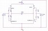
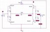
I built the presented circuit today for switching a single coil latching relay (1W, 5V rated):


I managed to switch the relay by changing the states of V2 and V3 - 0V and 3.3V states.

In switching mode (meaning V2 equals 3.3V, V3 equals 0v), the current that flowed from the 5V PSU was 250mA continuous, but the voltage drop on the relay was less than 1V.

I must say that I measured the relay's voltage after the switching of the relay and not during the switching.

There are two things that i dont understand:
1. The relay must consume at least 75% of 5V in order to change its state, how come that its coil's voltage (that shouldn't change after switching) was less than 1V?

2. Another problem that occured was that when both inputs V1,V2 were 0V, the current from the 5V PSU was 50mA.
It means that the current were flowing from the PNP collector to the base?
Should it happen?

Thank you very much for any help.
 

Attachments

  • relay.JPG
    relay.JPG
    29 KB · Views: 179
Last edited:
Seems like Q3 and Q4 are upside-down. The emitters should be connected to V1, not the collectors.

ken
 
All the emitters should point to GND.
V2 needs to be higher, try 5V. Also the transistors will drop 0.7V Use Logic level P & N channel MOSFETs if you can't afford the 1.4V loss.

Why start another thread on the same subject as your previous thread? What was wrong with using the TL4427?
 
Last edited:
Yes, i'm sorry, i didnt sketch it right,
Here it is:
 

Attachments

  • relay.JPG
    relay.JPG
    31.5 KB · Views: 176
Last edited:
All the emitters should point to GND.
V2 needs to be higher, try 5V. Also the transistors will drop 0.7V Use Logic level P & N channel MOSFETs if you can't afford the 1.4V loss.

Why start another thread on the same subject as your previous thread? What was wrong with using the TL4427?

Hey, Thanks for the help.
Here are my answers to you:
1.
I cant use higher V2,V3 inputs, because these are provided by MCU, which have only 3.3V GPIO pins.
2.
The place where i work has made recently an order, so i cant for now ask to order the TL4427.
3.
Why is the VCE of the trasistors will be 0.7V? I read in datasheet that its max VCE is 0.4V.

I would appreciate it if you could answer the 2 question i wrote in the post, now that i corrected the sketch.

Thank you very much.
 
OK so what's wrong with a dual coil relay? You're probably going to have to order parts sooner or later.

Dual coil relay consumes more power than single coil.

For now we try to use the single coil, thats why we built this design.
I'm trying to understand how to fix the problems that i encountered.
 
How so? It's only on very briefly and should consume the same current as an equivalent single coil relay. Plus driving it is far easier. What is its intended use?

You are right, but for now we're using the single coil.
I know that there are better solution to switch loads.
Our intended use is to switch up to 16Arms loads according to MCU directions.

Please, lets stay with this design for now, i'd really like to learn about it and about the problems i was encoutering.
 
Well this is your third new thread on exactly the same thing. I thought it was solved in the simple design that doesnt work. thread...
What was wrong with that FET design?
 
So add a single NPN transistor and 2 resistors on each side, as 3.3v to 5V level shifters.

ken
 
You have got to use this type of H-bridge, as explained to your before:
**broken link removed**
 
Last edited:
Well this is your third new thread on exactly the same thing. I thought it was solved in the simple design that doesnt work. thread...
What was wrong with that FET design?

I tried the FET design and it didnt switch the relay.
Could you help me please with the 2 questions i asked ?

please.
Thanks.
 
So add a single NPN transistor and 2 resistors on each side, as 3.3v to 5V level shifters.

ken

That could be a great idea.
Before we go to the next level (adding parts which make the design to cost more - we wanna go for mass prodution), i really want to understand what is wrong with this design, why the relay's voltage wasn't around 5V, and why was the stand-by current 50mA and not less?
 
Well you don't need Q1, Q2, Q3
You do need Q4 & Q9 plus the base resistors.

Transistors are how much? $0.02 or less in mass production quantities.
PS don't forget the four clamp diodes or your transistors wont last long.
 
Last edited:
The answers to your questions:

Your circuit will not work.
To turn off Q3 and Q4, the input voltage must rise higher than 3.3v - it must be higher than 4.5v.
You circuit draws current via the 190R resistors on each leg, via the base-emitter junctions of the transistors.
You need to see the principles of my circuit, posted above.
My circuit needs 220R (or higher) current-limiting resistors on the bases of Q6 and Q8 for a 5v supply.
 
That could be a great idea.
Before we go to the next level (adding parts which make the design to cost more - we wanna go for mass prodution), i really want to understand what is wrong with this design, why the relay's voltage wasn't around 5V, and why was the stand-by current 50mA and not less?

Did you turn your PNP transistors over? To turn the PNP transistors OFF, you need to drive their bases higher than V1-Vbe...+5V-0.6V...~+4.5V. +3.3V will turn the NPN transistors ON, but not turn the PNP's OFF. You need to do that the get 5V across the coil.

Not sure where your priorities are if you are talking mass production. A 2-coil latching relay, 2 resistors, and 2 transistors, would seem cheaper. Are you stuck on this design for some reason...like...no,I won't go there. ;)

Ken
 
Last edited:
The only way to create a new design that may be less complex is for you to fully explain what you want to do and provide all the parameters.
 
Status
Not open for further replies.

Latest threads

Back
Top