kinarfi
Well-Known Member
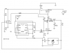
I've been playing with LEDs for my off highway vehicle and I think I have come up with a very viable power supply so you can drive as many LEDs as you want with them ALL in series(with in reason). It involves boosting the voltage a little above what is needed and regulating the current through all of the LEDs with one LM317. I haven't built the final prototype yet, but from what I have built, I'm sure it will work, I plan to drive 4 10 watt, 12.6V high output LEDs in series and another set of 26 3.2v 20 ma bright white 5mm LEDs. Generally, you can only put 3 or 4 of these in series and have to regulate the current of each set, this way you can probably run 20 or 30 in series. By setting the voltage just over what you need, the LM317 has enough head room to work with out generating a bunch of heat.
Feed back Welcome and suggestions welcome, I haven't determined what size caps should be used yet nor have I determined the correct diodes, however, I do know that they need to be high power and probably heat sinked.
Enjoy LED Folk,
Kinarfi
Feed back Welcome and suggestions welcome, I haven't determined what size caps should be used yet nor have I determined the correct diodes, however, I do know that they need to be high power and probably heat sinked.
Enjoy LED Folk,
Kinarfi
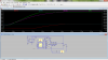
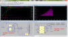
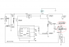
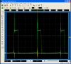
") I bought 3 of those LTC3783 and they got here today and I went to work making a circuit, but they are sooooooo small and the leads so delicate that I never got to put power on to try them, I couldn't even get the attached to the circuit board. I guess if you're going to use these devices, you need to get the $125 demo board or have circuit boards built for them, being a thru hole type person, all they did was cost money and frustrate me, after I a few wires hooked up and I tried to do another, I just managed to undo some of what I had already done. Probably are real nice circuit, but not for john Q public. Working on another method to accomplish my task. So far, here's where I'm at, got any suggestions? Haven't really tried it, but I have the oscillator running and using 600 v 20 amp fet. Need to figure out the right size inductor to use.
I bought 3 of those LTC3783 and they got here today and I went to work making a circuit, but they are sooooooo small and the leads so delicate that I never got to put power on to try them, I couldn't even get the attached to the circuit board. I guess if you're going to use these devices, you need to get the $125 demo board or have circuit boards built for them, being a thru hole type person, all they did was cost money and frustrate me, after I a few wires hooked up and I tried to do another, I just managed to undo some of what I had already done. Probably are real nice circuit, but not for john Q public. Working on another method to accomplish my task. So far, here's where I'm at, got any suggestions? Haven't really tried it, but I have the oscillator running and using 600 v 20 amp fet. Need to figure out the right size inductor to use.