Continue to Site

Welcome to our site!

Electro Tech is an online community (with over 170,000 members) who enjoy talking about and building electronic circuits, projects and gadgets. To participate you need to register. Registration is free. Click here to register now.

  • Welcome to our site! Electro Tech is an online community (with over 170,000 members) who enjoy talking about and building electronic circuits, projects and gadgets. To participate you need to register. Registration is free. Click here to register now.

power amp

Status
Not open for further replies.

danielsmusic

New Member
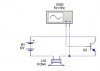
i was board at home with nothing to do so i thought i will build a audio amp using what i know about transistors.

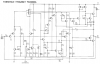
i built the schim below and it worked perfect. so why do ones that i open have so many components i know how to filter and that only has 4 components for bass and treble.

i used a car battery
 

Attachments

  • power_amp_554.jpg
    power_amp_554.jpg
    6.2 KB · Views: 900
Its good that you found something to do if you were bored.

But what you have drawn would not work perfectly. The transistor would only conduct on the positive half cycles. The ear may not be able to detect the difference with a sinewave input, but if you tried to play music, you may be a bit disappointed.

Audio amps need the parts to - ensure thermal stability and low distortion.

Len
 
i know what you are saying and i don't want to argu but i played music
and i could not tell any difference between my speekers and the transistor.

you must be right about + wave as a transistor will not invert a input.

my transistor was not geting hot.

any ideas?
 
Hi Dan,
Speaker cones are supposed to swing forward and rearward. Your transistor drives it in only one direction with the other direction missing. It will have severe distortion. Real amplifiers have a transistor like yours to pull the speaker in the positive direction plus a PNP transistor to push it negative.

Your transistor doesn't have any voltage gain. The speaker's output level will be very low when the transistor is driven by the 100mV signal from a tuner, tape deck, CD player or MP3 player.

The minimum number of parts for a speaker amplifier is 3 transistors, a few resistors and a couple of capacitors. The 3rd transistor provides voltage gain.
I would show an amp like that to you but it sounds like crap because it has such a few number of parts.

You could make a pretty good, cheap amp with a power amplifier IC. They use about 30 transistors but cost the same as two.
 

Attachments

  • tda2002_amplifier.png
    tda2002_amplifier.png
    49.2 KB · Views: 864
That's a weird transistor, isn't it?
It's a multiple-collector dual-base thingy that can't be purchased anywhere. All of its collectors have identical currents or something like that. When they make it, the collector currents can be a multiple of the others if the area of the collector on the chip is different (or something like that). :lol: :lol:
 
Looks like the days of employment for our Audioguru are numbered as now the secrets are out in the open.

High performance, excellent spec Single ended Pure Class-A amplifier, Flat response DC-5MHz. :lol:
 
Dose PNG make those lines look so crapy (some parts are thin some parts are thick)

Nice joke eblc but no fool wod make an audio amp have an respronse up to 5Mhz since no living creature can hear that.Audio amps even cut off high feq. on purpuse.

btw: cod you imagine how big an schematic wod be of an micorontroler IC. :shock:
 
Oh an i once got realy bored and made an realy simple audio amp out of an op amp IC and 2 power transistors.An low pass filter on the input made it sound prety good.Quite beter than my PC speakers.

The circuit was small enugh to fit on an 30 row breadboard whith no problem.I didnt make an schematic since you have lots of amps on the net.

The big amps(over 200W) mostly use PWM to do it.Becose this way much les heat is created and so much more power can be outputted.But these things get prety complicated.
 
eblc1388 said:
Looks like the days of employment for our Audioguru are numbered as now the secrets are out in the open.
Hi L. Chung,
Who me?
I've been sort of retired for about 5 years and don't have any more secrets. When my previous employers and customers call me to help them, say they are desparate and will pay me anything, I go. :lol:

High performance, excellent spec Single ended Pure Class-A amplifier, Flat response DC-5MHz.
The TDA2002 amp was class-AB and its response started dropping at 15kHz.
 
audioguru said:
I've been sort of retired for about 5 years and don't have any more secrets. When my previous employers and customers call me to help them, say they are desparate and will pay me anything, I go. :lol:

That's the reason they needed you. Some form of "secret" in the circuit design which they can't tackle.

High performance, excellent spec Single ended Pure Class-A amplifier, Flat response DC-5MHz.
The TDA2002 amp was class-AB and its response started dropping at 15kHz.

Nah. I meant the one Dan has designed & built, or how the sales department of a company would advertise it as. I'm afraid someone reading this forum may steal his design and offer no copyright compensation to Dan.
 
Someone Electro said:
Dose PNG make those lines look so crapy (some parts are thin some parts are thick)
The original PDF also looks crappy. PNG makes perfect copies.
I think Fairchild used a cheap scanner during an earthquake to make that copy. Texas Instruments also have some crappy copies of ICs from when they took over Harris Semi (previously RCA Semi). Their crappy copies of stuff from Burr-Brown are bad too.

no fool wod make an audio amp have an respronse up to 5Mhz since no living creature can hear that.
In order to perform properly up to 20kHz, an audio amp must have its bandwidth extend to 100kHz or more.

Audio amps even cut off high feq. on purpuse.
Usually external to the amplifier circuit, to reduce noise and inter-modulation. :lol:
 
Plenty of power amp designs here;

**broken link removed**

Most of the time, an IC solution is most practical. For some higher power situations though, or more specialised equiptment, discrete is the way to go.

I know about the complementary pair concept (a bit), but what is this "long tailed pair" I see on here? How does that work?

**broken link removed**
 
eblc1388 said:
Nah. I meant the one Dan has designed & built, or how the sales department of a company would advertise it as.
The sales department would advertise Dan's amp as having no noise at low levels (because it doesn't have any output with inputs less than about 600mV peak).
Right now his amp transistor operates in class-B. If he used a coupling capacitor to its input then it would operate in class-C for even more distortion.
I think Dan used heavy-rock music to test his amp or his hearing is haywire. :lol:
 
Dr.EM said:
I know about the complementary pair concept (a bit), but what is this "long tailed pair" I see on here? How does that work?

A "long tailed pair" is a VERY common configuration, used in the front end of most power amplifiers, and almost all opamps, it gives a differential input, and for a power amplifier the inverting input is used for the negative feedback - basically many power amplifiers are really just a high power discrete opamp.

Because the two transistors share a common emitter resistor (or constant current load) an increase of current in one transistor produces a decrease of current in the other. So each transistor effectively has TWO inputs, the normal one to it's base, and another one to it's emitter. In this type of audio amplifier it's usual to only use one of the differential outputs, so only one transistor has a collector load, the second connects directly to the HT rail.
 
danielsmusic said:
thanks, maby my transistor wasnt a transistor at all... :twisted:
Since it sounded pretty good and didn't get hot then maybe it was just a piece of wire. :lol:
 
Did it meaby conduct soo lite so it didnt get hot?

The the simple amp i did got the transistors at 45C° wen runing an 3,2Ohm speaker at norman loudnes.(The suply was 20 V)I had then on an heatsink from an old 200W PC PSU.

I was astounded how well that thing worked.It was just an op amp driving an power transistor trough an resistor.

Cod you stick that transistor in a multimeter for an Hfe test?
 
Status
Not open for further replies.

Latest threads

New Articles From Microcontroller Tips

Back
Top