Continue to Site

Welcome to our site!

Electro Tech is an online community (with over 170,000 members) who enjoy talking about and building electronic circuits, projects and gadgets. To participate you need to register. Registration is free. Click here to register now.

  • Welcome to our site! Electro Tech is an online community (with over 170,000 members) who enjoy talking about and building electronic circuits, projects and gadgets. To participate you need to register. Registration is free. Click here to register now.

Pioneer AV Receiver VSX-324 Power button issue

Hi all.

I have a Pioneer VSX-324 AV receiver whose only problem is the power button.
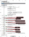
Schematic of the receiver: https://www.manualslib.com/manual/1027739/Pioneer-Htp-072.html?page=1#manual)

The problem I'm having is that when I use the remote to turn on the receiver, I just hear a click, but it doesn't turn on.

The only way to turn it on is to hold down the button for 2-3 seconds and it turns on without any further problem.

Holding the buttons down, I hear the clicks every fraction of a second, about 3-5 clicks. Then it turns on.

This problem started one day when I wanted to activate the receiver and TV using the remote control.

As far as I know, I've never had a power cut or power surge, nor a cable change. I have no other problems, such as sound quality or anything else.

I'm thinking that the problem may come from the button connection himself or maybe in that part of the circuit.
1691950935164.png


Do you have any ideas on how I should start looking for this problem?
Any help would be greatly appreciated.

Thank you very much.
 
Batteries in remote need replacing ?

Battery contacts in remote free from corrosion/oxidation ?

Remote IR window needs cleaning ?

IR photo detector in amp need cleaning ?

w/o a schematic tough

Regards, Dana.
 
Hi danadak, I'd say the remote is in very good condition.

The diagram is in the link I gave in my first post, but i'm adding the pdf in attachment. For me, the simple fact of having to click on the receiver's power button for 2 to 3 seconds makes me think that it must be the source of the problem.
 

Attachments

  • pioneer_htp-072_htp-073_vsx-324-k-p_s-22w-p_s-11a-p_sm.pdf
    19.7 MB · Views: 148
If you hear a click each time, the amp is presumably getting the signal from the button or remote OK?

Check for ripple or voltage drop on the standby power supply? I'd look at that and the main power relay first, as they are critical parts for the amp to switch on.
 
Thanks for your advice. I'm going to unplug the receiver this week and start examining it. I will examine the main power relay, as well and the standby power.

If I looked carefully, and I must admit I'm a beginner in electronics repair, the beow image would be related to the power button, and I see 4 capacitors (2 x 820pF, 1 x 10 nF and C761 that I don't know yet, but probably a 820pF as well), which I suppose could also be a reason why this problem could occur. Am I right to say this? I should use my capacitor discharge pen, and then test them.

1692011903073.png
 
I will examine the main power relay, as well and the standby power.
See page 71 of the service manual;
C31 and C303 are the most likely ones that could cause problems there.

The main power relay is RLY301 on the same page.

With a multimeter on voltage, test between CP701 pin 4 GNDU (negative) and pins 5, 6 and 9.
You should see close to 3.3V on pin 5 and somewhat more on 6 & 9 with the meter on DC.

With the amp on, check the same points with the meter on AC. (This may or may not work depending on the meter).

You should hopefully get a very low reading?

Post whatever voltages you get with each test?

Again with negative on pin 4, look at the voltage on pin 7 (on DC volts).
That should be under a volt, and show nothing on AC (if your meter is a type that can read voltage in this way).

Be very careful to stay away from the AC power wiring while doing tests!
 
OK, that looks like the white one above the red arrow?

If so, it appears you will be able to get to the solder side of the pins OK. Just be careful not to short anything & remember that PCB also has 240V AC on it in other places, at the transformer and beyond!
 
HI again. After many months, and also after studding basics on electronic, i have decided to look at it today.

Sorry for the delay [B]rjenkinsgb[/B]

I decided to change the capacitors on the primary power rail (4 of them). One of them looked suspicious, but in the end, all turned out fine. Still, I decided to put in new quality capacitors.
1704846900560.png


Then, after a few tests, on the 9-pin connector, the result is:

The pin 5 CPU_+3.3v = 3.29v
The Pin 6 CPU_ST_VCC = 10.24v
The Pin 9 CPU_ST_VCC = 10.24v

I get a lower reading once On. Ex 7.04V on pin 6 and 9.
But 5.02v on pin 5.
With negative on pin 4, the voltage i get on pin 7 is 12.1 mv when Off, or 32.0mv when On.

So I decided to change the RlY301 relay. It was originally a JZC-36FD, replaced by an SDT-S-105DMR with the same characteristics, thinking that even if clicks occurred, it could work partially, which is why I needed to hold down the front panel button for 2 clicks for the device to finally switch on.

New relay:
1704846949695.png
1704846969810.png


After testing it, I was still faced with the same problem.

On 2 of the relay pins, I have 10.13v. From what I understand, and if I'm right, this seems to be good.

I cleaned the buttons on the front panel.

After all that, I still have the same problem.

I try to do a reset by holding down the Power button and the Band button at the same time, but as I need at least 2 clicks to turn the amp on, it does nothing.

Now I'm wondering if it's a microchip.

What do you think?

Thanks again for your help. I'm continuing to search.

1704847148583.png
 
Last edited:
Hi again. Ok, after a few more tests, and according to the picture below, fuse F301 is good.

Now if I look at the voltage at the next stage on C301, I have 10.41 volts. But on pins 6, 9, I have zero volts.

So, according to the picture, it says "Replace STBY assembly".

I guess to replace the STBY Assy, both pins (6, 9) and C301 would have to be below 5.6V. But if one of them is at 10V (capacitor), there may be something else on the STBY Assy circuit or elsewhere.

Any ideas or thoughts?

I still have to point out that if I hold down the Power button for about 3 seconds, after 3 clicks, the amplifier turns on.

I've heard that such power supply problems could be due to a faulty capacitor. But clearly not on the STBY Assy.

I'll keep looking into it.

Thank again.
1706399392839.png
 
New update, as I go down the "No power" troubleshooting list, again No power with a single click, but powered up when I hold down the "Power ON" button for 3 seconds. Looks like i'm getting closer to the CPY Assy.

1706454815690.png
 

Attachments

  • No Power.jpg
    No Power.jpg
    157.6 KB · Views: 58
New Update:

All validations have been carried out and all required results have been confirmed as expected. At the end of the "No power" troubleshooting list, it now say "Replace CPU Assy". But then again, there's no power with a single click, but the unit turns on when I hold down the "Power ON" button for 3 seconds.

I'm now thinking it could be the CPU Assy, or one of its components such as a capacitor or Mosfet, or maybe just a solder crack somewhere between CP701 to CN701 to CN705 to CN704B that's about to go out, which would explain why I have to force the power clicks to turn the unit on.

What do you think?

1706462912755.png
 
sound is good but what about contact voltage?
 
I'm really starting to think it could be something as small as a cracked solder component. So far, everything looks OK. I'm now testing by trying to check things a bit, or even moving the cables around a bit, if I could find something?

What do you think?
 

Latest threads

New Articles From Microcontroller Tips

Back
Top