Continue to Site

Welcome to our site!

Electro Tech is an online community (with over 170,000 members) who enjoy talking about and building electronic circuits, projects and gadgets. To participate you need to register. Registration is free. Click here to register now.

  • Welcome to our site! Electro Tech is an online community (with over 170,000 members) who enjoy talking about and building electronic circuits, projects and gadgets. To participate you need to register. Registration is free. Click here to register now.

pic24fj breakout

dougy83

Well-Known Member
Most Helpful Member
I made some simple breakout boards for pic24fj256ga705 a while back, but never managed to have the pickit3 recognise a device on any of the boards. Does anyone have any experience with this processor family?

The VCAP is actually a 10uF/50V X7R, and has ~1.8V across it. The datasheet is quite particular about this needing to be a higher voltage part. The only other thing I noticed regarding programming requirements is that the ICSPCLK/ICSPDAT pins must be used as a pair (as there are multiple pairs), which I believe I've done.
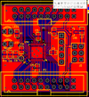
 

Attachments

  • schem.pdf
    170.6 KB · Views: 196
  • pcb.png
    pcb.png
    150.6 KB · Views: 166
I've not used that exact device, but I have used a lot of DSPIC33E & F series ones, which are near identical.

I don't see any obvious problems from a quick look at the circuit?

You do need to define which set of debug pins you are using somewhere, for devices that have more than one set.
For the CCS compiler I use, it's in a line near the start of the program - eg.

#DEVICE DSPIC33EP512GP502 ICD=1 adc=12

I use the ICD3 or now ICD4 for programming & debugging.
 
Are you really using 22uF for the VDD/VSS decoupling caps (C4, C5, C6)?
Normally they would be more in the range of 0.1uF ceramic

Make sure you have the FICD CONFIG register set for JTAGEN=0 (jtag disabled), ICS=11 (PGC1/PGD1)
 
...have you used it with the stand alone PK3 program.
You raise a good point there...
to the OP - what program are you using?

I don't think the stand-alone PK3 v3 app would support the 24fj256ga705...
you'd have to be using a modified dat file, mplabx, PICKit+, or PICKitminus
 
Thanks for the responses, and for having a look at the circuit. The device is not recognised by the programmer, so the config bits don't yet have a chance of causing issues. The PK3 works fine for a pic16f677 I have on hand. I'm guessing it's most likely a soldering issue, or as Nigel mentioned, the issue with multiple ICSP pins.

I'll assemble another next week in a lab with decent tools, so that should be able to rule in/out the soldering issue.
 
I don't think the stand-alone PK3 v3 app
If PK3 has been used on the stand alone program with any device , it wont work on MPLABX . I always put a 100R between pin 1 on PK3 and mclr pic pin , along with a10k from the Vcc , Where is the 3.3 v power coming from ?
MC Snap is quite a good economical programmer ,
 
If PK3 has been used on the stand alone program with any device , it wont work on MPLABX . I always put a 100R between pin 1 on PK3 and mclr pic pin , along with a10k from the Vcc , Where is the 3.3 v power coming from ?
MC Snap is quite a good economical programmer ,
I've not heard of any such issue with the PK3 and MPLABX?, it should just upload the correct firmware, and he's got a 10K from Mclr to Vcc, it's R3.

I presume he's powering the circuit from the PK3?, which could be a problem if he's got anything else connected, not shown in his circuit - as the PK3 can provide VERY little power, it's worth upgrading to the PK4 for that alone.
 
I've not heard of any such issue with the PK3 and MPLABX?
Granddad's right... the PK3 firmware used with the old standalone programming app (or MPLAB 8) isn't compatible with MPLABX, so if you switch back and forth between the two you must force it to download new firmware each time. Royal PITA.

dougy83 - you never answered my question about which programming software you're using.
 

Latest threads

New Articles From Microcontroller Tips

Back
Top