Hello.
I am writting a program where at the beggining i declare which variables are used in the program using
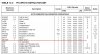
When i run the simulator i can see that these registers are messed up as variables are declared elsewhere in the GPRs. They are declared at 0A0h instead of 020h.
any help?
the pic i am using is 16f873
Thank you
I am writting a program where at the beggining i declare which variables are used in the program using
Code:
cblock	h'20'
			timer0
			timer1
			NumL
         huns
			tens
			ones
			BIN
	endc
When i run the simulator i can see that these registers are messed up as variables are declared elsewhere in the GPRs. They are declared at 0A0h instead of 020h.
any help?
the pic i am using is 16f873
Thank you