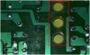
What is the purpose of the holes that are drilled on the PCB's under transformers?
They are present in almost any AC/DC charger that I have on hand.
I don't think that the holes are drilled to maximize air flow through the transformer, because most converters are mounted inside plastic boxes with no air flow.
These holes clearly do not provide insulation (primary to secondary sides of the transformer), they are drilled on copper-free areas that already meet insulation requirements.
I thought that they are drilled for mechanical concerns during assembly or wave soldering, but I could not find any useful documentation on the web. Does anyone have experience with this tecnique?
Thank you.