Continue to Site

Welcome to our site!

Electro Tech is an online community (with over 170,000 members) who enjoy talking about and building electronic circuits, projects and gadgets. To participate you need to register. Registration is free. Click here to register now.

  • Welcome to our site! Electro Tech is an online community (with over 170,000 members) who enjoy talking about and building electronic circuits, projects and gadgets. To participate you need to register. Registration is free. Click here to register now.

opamp woes

Status
Not open for further replies.

frosty12345

New Member
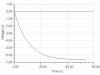
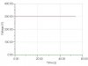
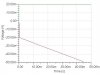
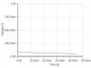
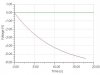
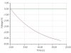
using an ideal opamp in the configuration shown, i get the 20mV step response as shown. if i use the tl81 opamp, the step response is completly different. can anyone suggest anything to enable me to get a better step response?

thanks
alex
 

Attachments

  • circuit_165.jpg
    circuit_165.jpg
    9.3 KB · Views: 419
  • lag_ideal_1_20m_step.jpg
    lag_ideal_1_20m_step.jpg
    23.4 KB · Views: 405
  • lag_real_1_20m_step.jpg
    lag_real_1_20m_step.jpg
    17.8 KB · Views: 413
Completly different from? A different opamp maybe?

In reply mode, I can not see the circuit now. What is the gain you are going after? The TL081 is a good op-amp.

Went back to look, 100 range..

What are you tring to achieve with this circuit?
 
The circuit appears to have a DC gain of about 1 so I am puzzled how the ideal output could trend towards a steady state value of -6.6 volts if your input step is only 20 mV. It is also kind of puzzling to see the "real" output at 300V. So it would be useful to know what power supply rails you have specified for the real circuit. Could you let us know?

I am wondering if the real circuit has railed at its maximum output voltage. This might be caused by DC bias problems. One possibility is to look at the input bias current required by the TL81 and consider that this bias current has to flow through a 10M resistor which is an awfully large value. Even if you have only 1 nA of input bias current, you will see a voltage drop across the resistor of 10mV which will then be amplified by 330 at the second opamp stage so you will see an output error of 330*10mV = 3.3V. So you can see that the input bias current may have a significant effect of adding DC voltage to the output and if this is too big, the output may hit the power supply rail. the obvious thing to try in this case is to lower your R1 and R2 values by, say, two orders of magnitude and see if the response improves.
 
Oops, just realized that the AC gain is 1, but the DC gain is 330, so input value of -20 mV will indeed provide output of -6.6 Volts, so now I understand the ideal output curve. My comment on the input bias current is still valid though.
 
the circuit is a controller so the desired response is just the step response - however, its only required over a short period so ive attached a new desired response. on my simulation of the "real" circuit, i had forgotten to add a ground so that was causing part of the problem.

The requirements of R1, R2 and C are that:

1/(R2*C) = 33
1/((R1+R2)*C) = 0.1

and they were chosen arbitrarially to be the values shown in the figure.

ive attached a new step response of the "real" curve. is the difference in real and ideal caused by the input biases?

thanks for the help
 

Attachments

  • ideal2.jpg
    ideal2.jpg
    25.7 KB · Views: 394
  • real2.jpg
    real2.jpg
    21.5 KB · Views: 385
Your graphs only show the first few tens of milliseconds while the time constants involved are many seconds, so we need to see the x axis up to, say, 10 or 20 seconds. Can you plot those?
 
//re-added post

they dont look too bad now using that scale
 

Attachments

  • lag_ideal_20mv_step_20sec.jpg
    lag_ideal_20mv_step_20sec.jpg
    23 KB · Views: 362
  • lag_real_20mv_step_20sec.jpg
    lag_real_20mv_step_20sec.jpg
    23 KB · Views: 356
Things are looking better now. You can see there is a DC difference between the two, but looks like only about 0.1 volts or less. This difference may be due to input bias current. I haven't looked at TL81 lately, but if it is FET input type of op amp then input bias current is nearly zero, so no problem with the 10 Mohm resistance.
 
thanks for the help so far.

i was hoping to use this circuit at low voltages <1V, so a 0.1V offset might be an issue. is there anything i can do to remove this bias?

my simulation software says that a tl081 has:
input V offset: 5m
input I bias: 30p
input I offset: 5p

in practice i have nothing connected to the bias pins on the chip.

regards
alex
 
The input Voffset of 5 mV may be a problem. Since you have a DC gain of 330 in the second stage, that offset will be multiplied by 330 to give you around 1.6 volts in the worst case. There are a couple of ways to deal with this. One is to AC couple at the output at a very low cutoff frequency, but of course this would totally mess things up if you really want a DC response in your application. Another thing you can do is to sum a bit of additional voltage into the input of the second stage to compensate for the offset voltage of the op amp. This is usually done with a simple voltage divider from +supply to -supply which is tapped somewhere near the middle, maybe with a pot, and fed into the inverting input alongside your 1K input resistor. The voltage divider uses higher values than your feedback resistor 330K so that the DC gain from this network is low. The problem with this idea is that it doesn't correct for offset voltage drift vs temperature. The other problem is that your circuit suddenly becomes sensitive to DC voltage drift of your supply rails, subverting the PSRR of the op amp. Another solution is to choose an op amp that has much lower input Voffset.

By the way, those values of input bias current are so low that we don't need to worry about that too much. But be careful when you use such high value input resistors. 10 Mohms is very high. A little bit of humidity condensing on the pcb will mess that up. Another practical problem is that the leakage current of your shunt capacitor may be too high for that 10 Mohm resistance.
 
Status
Not open for further replies.

Latest threads

New Articles From Microcontroller Tips

Back
Top