Continue to Site

Welcome to our site!

Electro Tech is an online community (with over 170,000 members) who enjoy talking about and building electronic circuits, projects and gadgets. To participate you need to register. Registration is free. Click here to register now.

  • Welcome to our site! Electro Tech is an online community (with over 170,000 members) who enjoy talking about and building electronic circuits, projects and gadgets. To participate you need to register. Registration is free. Click here to register now.

Opamp problem--I think

Status
Not open for further replies.

Torben

Well-Known Member
Hi all,

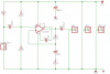
I'm getting an interesting result from a simple mic preamp I'm building. The schematic should be attached.

First off, I'm using VA's (Visual Analyzer--freeware soundcard scope program) frequency analysis to check the response. At low to medium gains and with good amounts of input, the response line looks really good--a nice clean line from ~20kHz (the highest you can see on this soundcard) which starts dropping at around 300-400Hz and looks like it would hit unity right around DC (can't see down to DC on this thing either).

However, in silence or near-silence, the response graph goes all over the place. When I provide sound into the electret the graph line cleans right up. Of course, providing too much input overdrives it and the line goes to hell again, but I expect that.

Note about the schematic: I don't actually have a TL081 in there at the
moment; it's a 5534--hence the 47pF compensation cap.

For reference, this is for an acoustic guitar mic--I've got the response pretty much tailored to where the mic element is sitting inside my guitar at the moment. No lack of bass there. I can, however, overdrive the thing by playing hard enough. It actually sounds pretty good through my mixer and monitors, but I can hear a bit of noise still.


Questions:

1) Is it normal to see the response graph go crazy with little or no input? Or is the thing just basically unstable, needing input to stabilize it?

2) Currently I am using 5% resistors across the board, but matched the 47K divider resistors with a meter. I understand that there are other reasons to prefer precision resistors--temperature stability, degradation over time, higher Johnson noise, etc--so I've got some 1% ones to try. Figure it's worth it?

3) Could I make it harder to overdrive this thing by upping the power supply current? At the moment I've got it set up with a 9V battery for power, but if I'm calculating it right, this thing should really only last about 5-6 hours on a regular 9V. Anyway, initial testing with VA seems to show that I don't really get more resistance to distortion by upping the supply to, say, 15 or 18 V. But I've read that you get better headroom with increased supply. I guess I'm not really understanding what that means.


Thanks,

Torben
 

Attachments

  • preamp_1_with_comp_cap.png
    preamp_1_with_comp_cap.png
    6.8 KB · Views: 671
What's the function of C2? Are you trying for treble emphasis? It's going to introduce some interesting phase shift in your feedback - this may be why your output is squirrely with no input. Jump it out and see what happens.
 
C2 is in proper place, and at that value u'll affect most audio range. What worries me is the very low gain u set for a mic preamp and the very high value of the input capacitor. Now u said that it only goes crazy with little or no input. what do u mean ? Is the mic hooked but u stay silent? or the mic is not hooked and u leave the input with no signal? Cuz if the mic's hooked even if u stay silent it will pick up noise.
 
j.p.bill said:
What's the function of C2? Are you trying for treble emphasis? It's going to introduce some interesting phase shift in your feedback - this may be why your output is squirrely with no input. Jump it out and see what happens.

The explanation for C2 is probably best left to Uncle Scrooge in the last post of this thread: https://www.electro-tech-online.com/threads/electret-preamp-layout-question.27348/

What I take that to mean is that it's there to get rid of potential voltage differences between the inputs (um...is this the same as saying it's reducing DC bias on the input?) so that there is the same headroom above and below the 0V point, letting the opamp go as possible or negative as needed within current conditions.

Past that I'm still pretty foggy. The phase stuff I couldn't comment on. I've got a bit of work to get out of the way but I'll give skipping the cap a try in a few minutes.


Thanks,

Torben
 
Capacitor.

Hi Torben,

Don't skip the capacitor, the output voltage of the opamp
will saturate. (maximum positive output voltage.)
The reason why the capacitor is there is to reduce the dc
gain to one keeping the ac gain at 3,2.

on1aag.
 
hentai said:
C2 is in proper place, and at that value u'll affect most audio range. What worries me is the very low gain u set for a mic preamp and the very high value of the input capacitor. Now u said that it only goes crazy with little or no input. what do u mean ? Is the mic hooked but u stay silent? or the mic is not hooked and u leave the input with no signal? Cuz if the mic's hooked even if u stay silent it will pick up noise.

The mic is hooked up. If I keep quiet, the response line goes crazy. If I rub my hands *hard* about 4cm from the mic, the line settles down somewhat. If I speak normally close to the mic, the line settles down while I'm hitting loud vowels or popping into the mic. With a white noise source clipped on just between the electret and the input cap, the line settles right down.

Haven't measured the voltage on the white noise signal. If I turn it right down, response goes nuts. Turn it up slightly less than midway, and the response line is great. Turn it up past there and the response gets really distorted, but on average retains its general curve (though with at LOT of input you have to use some imagination to see it).

The higher I push the gain, the less forgiving the amplification is to distortion. I don't yet have the experience to know how to get the best of both worlds, which is part of what I intend to learn from this project.

I've tried different values for the input cap, down to 0.1uF. I didn't think I was cutting enough low end with those, but I'll try it again and see what it sounds like.


Thanks,

Torben
 
post some screen shots pls. and increase the gain that mic outputs a few milivolts. the distorsions u get might be from ur soundcard. did u hooked it at the mic input of ur soundcard?
 
Your original circuit had a 22k negative feedback resistor for a voltage gain of 23. This circuit has it changed to 2.2k for a voltage gain of only slightly more than 3.
Your original circuit had input and output capacitors of 10uF for a low frequency cutoff of only 0.6Hz. This circuit has them changed to 220uF and it will take them a long time (25 seconds) to charge. I would use 330nF for a cutoff frequency of 18Hz.

Don't you have shielded audio cable connected to the microphone?

Some opamps oscillate at a very high frequency when they drive the capacitance of a shielded cable. Add a 100 ohm resistor in series with the circuit's output if it drives a shielded cable.
 
audioguru said:
Your original circuit had a 22k negative feedback resistor for a voltage gain of 23. This circuit has it changed to 2.2k for a voltage gain of only slightly more than 3.

Right...I had been reading about op amps getting better responses with less gain, but I'm still working out where the sweet spot might be. I'll try going for more gain again.

Your original circuit had input and output capacitors of 10uF for a low frequency cutoff of only 0.6Hz. This circuit has them changed to 220uF and it will take them a long time (25 seconds) to charge. I would use 330nF for a cutoff frequency of 18Hz.

My mistake--typo in the schematic. Those are actually 220nF, not uF.

Don't you have shielded audio cable connected to the microphone?

Actually the mic element is currently 1 resistor away from the op amp input...no cable at all. I will use shielded cable when installing it, though.

Some opamps oscillate at a very high frequency when they drive the capacitance of a shielded cable. Add a 100 ohm resistor in series with the circuit's output if it drives a shielded cable.

OK, I'll definitely give that a shot. I certainly don't intend to not use shielded cable to the mixer, so I'll probably just put one in permanently.

Actually the next preamp is probably going to be phantom powered, so I can hopefully make use of some of the extra voltage (although I understand that the current available will likely be low).


Thanks for the tips!

Torben
 
Torben said:
Actually the next preamp is probably going to be phantom powered, so I can hopefully make use of some of the extra voltage (although I understand that the current available will likely be low).
be carefull with that phantom power on opamps. U must use a regulator to drop the voltage so that it will be safe for the opamp.
 
audioguru said:
Your original circuit had a 22k negative feedback resistor for a voltage gain of 23. This circuit has it changed to 2.2k for a voltage gain of only slightly more than 3.
Your original circuit had input and output capacitors of 10uF for a low frequency cutoff of only 0.6Hz. This circuit has them changed to 220uF and it will take them a long time (25 seconds) to charge. I would use 330nF for a cutoff frequency of 18Hz.

OK, I jumped the 220nF input cap with a 100nF...so that should now be a total of 320nF. Now...how do I work out Fc for myself? I've found a couple of formulas but none of the circuits seem to match the one I have here. Or rather I'm still not quite able to reduce the one I have to match any of those presented in wikipedia, AoE, or Analog Device's filter design java applet.

Ah yes...I also upped the feedback resistor from 2K2 to 10K for a gain of 11, and replaced the 47K divider resistors with a pair of 1% 46.4K resistors. Didn't appear to make much difference on the breadboarded test circuit--I suspect because the breadboard is crappy enough to swamp any improvement--but it does seem to sound a bit better on the PCB version (which is taped to my guitar).


Thanks,

Torben
 
The calculation of the cutoff frequency (frequency at which the response is down 3dB which is an amplitude of 0.707) is with the total impedance and the value of the coupling capacitor.

The electret microphone is effectively in parallel with the 10k resisor that powers it. Their total impedance is about 3.3k ohms.
The two 47k resistors are effectively in parallel with a total resistance of 23.5k ohms.
The input of the opamp is a very high resistance and can be ignored.
The 3.3k is in series with the 23.5k producing a total resistance of 26.8k ohms.
The formula is 1/(2 pi RC)= 27.1Hz for 220nF and 18.7Hz for 320nF. Your guitar cannot play anywhere near as low so the sound will be the same.

The 47k resistors bias the input of the opamp to half the supply voltage. If their values are not exactly the same there won't be any difference in the sound until the opamp is clipping which means its gain is turned up too high.

A breadboard makes amplifiers oscillate. Use a pcb instead.
 
audioguru said:
The calculation of the cutoff frequency (frequency at which the response is down 3dB which is an amplitude of 0.707) is with the total impedance and the value of the coupling capacitor.

The electret microphone is effectively in parallel with the 10k resisor that powers it. Their total impedance is about 3.3k ohms.
The two 47k resistors are effectively in parallel with a total resistance of 23.5k ohms.
The input of the opamp is a very high resistance and can be ignored.
The 3.3k is in series with the 23.5k producing a total resistance of 26.8k ohms.
The formula is 1/(2 pi RC)= 27.1Hz for 220nF and 18.7Hz for 320nF. Your guitar cannot play anywhere near as low so the sound will be the same.

OK, that explains a lot. I'm going to play with my calculator for a while now.

A question, though...I've read that keeping the gain at 0dB at DC is desirable for stability. Is reducing it to below 0dB a problem, or will the op amp not attenuate the signal below 0dB gain, or is it just not relevant? Or am I misunderstanding the applicability of this particular hint entirely?

The 47k resistors bias the input of the opamp to half the supply voltage. If their values are not exactly the same there won't be any difference in the sound until the opamp is clipping which means its gain is turned up too high.

Let's hear it for the placebo effect, then. It's why I said "seems"--I trust my ears, so if the difference isn't immediate then I don't trust that it's actually there. :)

However, I still have a question about that: if the divider resistors are NOT accurately matched, will I not lose some headroom before clipping (either above or below 0)?

A breadboard makes amplifiers oscillate. Use a pcb instead.

Will do. Am doing. Whatever. I enjoy making the PCBs but I'm not quite fast enough at it that I'm willing to run one off for a fully untested design just yet though--still need a better grasp of the math and theory. But I'll remember not to trust them in this regard (at least--breadboards also have other problems like weak contacts etc).


Torben
 
Torben said:
I've read that keeping the gain at 0dB at DC is desirable for stability. Is reducing it to below 0dB a problem, or will the op amp not attenuate the signal below 0dB gain, or is it just not relevant? Or am I misunderstanding the applicability of this particular hint entirely?
C2 lets the opamp have AC gain but have a DC gain of 1. It doesn't have any DC gain, its DC output voltage is exactly the same as its DC input voltage (from the two 47k resistors).
 
audioguru said:
C2 lets the opamp have AC gain but have a DC gain of 1. It doesn't have any DC gain, its DC output voltage is exactly the same as its DC input voltage (from the two 47k resistors).

OK, great. The sad thing is that this makes so much sense I wish now I'd just thought about it a little harder. :)

Thanks for all the explaining!


Torben
 
Status
Not open for further replies.

Latest threads

Back
Top