featherheart9
Member
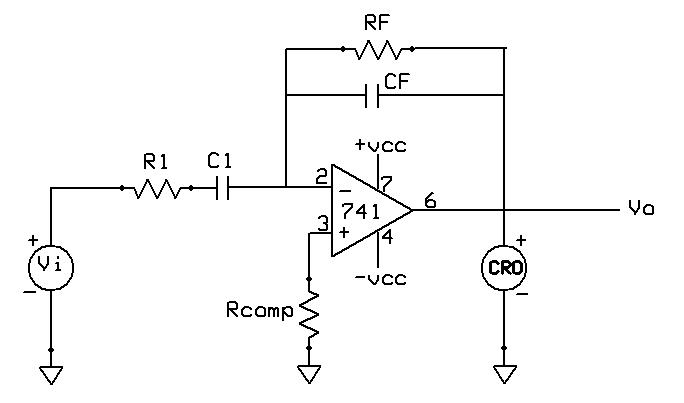
In the book opamps and linear integrated circuit by gayakwad
it is given that if we have to design differentiator using opamp
the following methods should be followed
1.select fa equal to highest frequency of input signal to be differentiated.then assuming a value of C<1microfarad calculte Rf.
2.choose fb=20 (fa) and calculate values of R1 and Cf so that R1 C1=RfCf
so my question is if we are using it for input signal of say 10 Hz to 1kHz then why we should equate fa=1kHz.
because it will work as differentiator in the range fa to fb .so fa should be 10 Hz nd fb should be 1kHz..
please explain why we use this method for designing

