Continue to Site

Welcome to our site!

Electro Tech is an online community (with over 170,000 members) who enjoy talking about and building electronic circuits, projects and gadgets. To participate you need to register. Registration is free. Click here to register now.

  • Welcome to our site! Electro Tech is an online community (with over 170,000 members) who enjoy talking about and building electronic circuits, projects and gadgets. To participate you need to register. Registration is free. Click here to register now.

Op Amp oscillator not oscillating.

Status
Not open for further replies.

Fluffyboii

Active Member
Today I had an idea. I wanted to have a Low frequency Oscillator with lm13700. Music From Outer Space has circuit diagram of one that has sinus wave output. But I know there are Voltage Controlled Low Frequency Oscillators with the same IC. The bottom diagram is voltage controlled but it lacks sinus output.
1662412398787.png

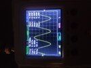
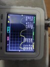
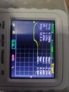
This circuit uses one of the LM13700's OTAs for LFO and another for Voltage Controlled Amplifier. But I don't want to have VCA for now so I did not build the right section of the circuit in the image and connected the triangle output of it to Music From Outer Space's LFO's triangle to sinus converter section that uses the second OTA. At the end I combined those two circuits to have a VCLFO that also has sine wave with square and triangle. My problem is that this thing doesn't want to oscillate. When I touch the pin 1 of LM13700 with my multimeter prop or tweezers I can see that a signal is created on sine output. And when I touch the other input of the lm13700 (trig out) there are similar signals being generated on sinus out accordingly. I can also see that these small voltage spikes are actually being distorted into a somewhat sinus wave with my oscillator. Triangle and square outputs also get spikes but no continuous waves are appearing. I checked and messed with pots and such and couldn't get it going.

I forgot to mention that I buffered the triangle and square outputs with tl074's other two op amps. I used tl074 instead of tl072 for specially buffering those because I know that oscillation won't happen if outputs get loaded even a tiny bit from my past experiences. Triangle is buffered like this:
1662412921418.png

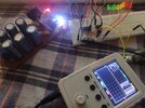
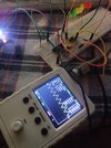
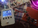
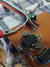
I can't really spot a problem after all. I will check it tomorrow since I am very tired today. I add the images of the circuit I made but it is very tightly soldered (bad habit of mine) so I am not expecting anyone to spot a problem on it. I know someone will ask so: All of the ICs are original, I am not naive enough to trust Chinese ICs. I first test with original ones then see if the ones I got from China works or not and then put them in if I want to preserve guaranteed original ICs.
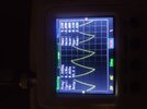
1662413597137.png

1662413655100.png

1662413691231.png
 
Just a thought but build the essence of the oscillator on a breadboard first,
just the main loop, and get that working. To produce a clean tri wave.

1662415507763.png


From the datasheet replace the second amp with your comparator solution, get that working.

1662415825013.png


Regards, Dana.
 
Just a thought but build the essence of the oscillator on a breadboard first,
just the main loop, and get that working. To produce a clean tri wave.

View attachment 138429

From the datasheet replace the second amp with your comparator solution, get that working.

View attachment 138430


Regards, Dana.
It is showing the same exact behaviour. It is stuck at +3.04V (exactly same number) and some waves appear if I touch stuff but no oscillation.
 

Attachments

  • IMG_20220906_023125.jpg
    IMG_20220906_023125.jpg
    6.6 MB · Views: 191
Ok my bad got it going now. This confirms that there is something wrong within a specific part of the circuit at least.
 

Attachments

  • 16624219043415104477114952976983.jpg
    16624219043415104477114952976983.jpg
    1.9 MB · Views: 185
At its most basic level, as an amp, can you show your 13700 is not bad ?

I have built that basic osc in datasheet 30+ years ago, it worked.

Your capacitor is not mismarked and actually in the pF range....?


Regards, Dana.
 
danadak Looking at the breadboard made me realise the mistake and I fixed it. Non inverting out of LM13700 was connected to output of tl074 instead of non inverting input. Chinese lm13700 I got for 1/5 of local price are working.
Sine wave is bit dodgy though. It looks like It can go down to 8Hz but sine wave becomes garbage and triangle is not triangle anymore at that point. I guess I need to adjust resistor and capacitor values if I want to go slower without that much distortion.
 

Attachments

  • IMG_20220906_030535.jpg
    IMG_20220906_030535.jpg
    6.1 MB · Views: 195
Last edited:
That's a cool handheld scope you've got there? What brand is it?
This one, I got it from Aliexpress. It does the job for me.
Excellent, do you have access to a scope with FFT ?

Or do this which will give you a spectrum analyzer, f(0) generator, etc...

But protect your sound card inputs first as suggested here (posts 10 and 12) -


Regards, Dana.
My collage might have those. After summer holiday ends I can test it out there. I changed the triangle buffer stage of my op amp to a non inverting amplifier of 100k/33k which made the sine much better. Triangle still turns into that time constant-ish book example when I go too slow.

I will check the article about sound card oscilloscope. Is it needed for testing the purity of the sine wave?
 

Attachments

  • IMG_20220906_034557.jpg
    IMG_20220906_034557.jpg
    4.8 MB · Views: 181
  • IMG_20220906_034703.jpg
    IMG_20220906_034703.jpg
    4.8 MB · Views: 178
The sound card oscilloscope gives you a spectrum analyzer, audio range, you can
look at to get an idea of harmonic distortion.

https://www.zeitnitz.eu/Scope_en Below I used its function generator to create a 6 Khz sine
and fed it into its oscilloscope/spectrum analyzer

1662430870492.png


On triangle wave keep in mind slew rate limitations of OpAmps and max freq
and V they can generate before going into slew rate distortion.


Regards, Dana.
 
I removed the high pass filters I added because the frequency and the values of capacitor and resistor were too low and it was pointless in something that supposed to oscillate at low frequencies. There is still a high pass filtering effect at output when I decrease the frequency too much. I tried increasing the capacitor value of 330n with adding 1uf parallel but the behavior did not change. Basically under 10Hz square wave and triangle wave starts distorting like they were passed on a RC high pass filter. The voltage keeps decreasing when the frequency is lower until it zeroes.

Second thing is: Normally voltage controlled oscillators start oscillating at higher frequencies when the voltage at their inputs are higher at something like 1V per octave. This one acts in reverse. When the voltage at input is high the frequency is low. The voltage at the 1st pin of the LM13700 is always negative and when the voltage is closer to -12 the frequency is lower.
 
Last edited:
When you get down to that low a frequency leakage starts to rear its ugly head
as well. What kind of caps were you using ?


Regards, Dana.
I think am using ceramic ones 100nf and one 220nf parallel connected. But they look like tantalum caps because of the shiny outside finish yet I have no idea how to identify since only thing written on them is their capacitance. Maybe I should try using 3x 100n regular film ones.
The low frequency high pass behaviour always happens with op amp oscillators for some reason. Normally changing capacitor or resistor values changes the point it starts happening but in this circuit uses lm13700 to charge the caps so idk maybe it is why.

Is it normal that pin 1 of the lm13700 is always at a negative voltage. I checked the transistor connections to see if anything was wrong that might be causing the frequency to go down instead of up with more CV input but can't find a problem.
 
Last edited:
Yes on pin 1, you are looking into a current mirror which will always be ~ 2 * Vbe above the - rail.
The two Vbe = Vbeq1 + D1 fwd voltage.

You say the Tant C is 100 nF, .1 uF, that does not seem right. In any event can you use a
low leakage cap for that and try the low freq test again....?


Regards, Dana.
 
You say the Tant C is 100 nF, .1 uF, that does not seem right. In any event can you use a
low leakage cap for that and try the low freq test again....?
It is probably just a fancy ceramic capacitor. I don't have specific low leakage caps on hand but I will try with some other caps.

Ok found out that those caps are called multilayer caps with 63V max rating.
 
I installed these film caps since it was listed better leak graph than ceramic ones but it didn't really had an effect.
 

Attachments

  • IMG_20220908_012142.jpg
    IMG_20220908_012142.jpg
    1.3 MB · Views: 172
  • IMG_20220908_012147.jpg
    IMG_20220908_012147.jpg
    1.3 MB · Views: 165
  • IMG_20220908_012218.jpg
    IMG_20220908_012218.jpg
    1.2 MB · Views: 173
What is your actual goal in performance specs ?. I dont think of the LM13700 as a high precision
device, and am guessing its leakage current that is causing this. The bias current leakage, the limited
output current, etc...

If I were to tackle real low freq I would do this with lookup tables and a DAC and A/D (to get the
control V to translate to clock rate needed for LUT/DAC combination.

So what are you performance specs you are seeking ?

1) Range of freq ?
2) Harmonic distortion for sine ?
3) Output level flatness ?
4) Latency from V to F response ?


Regards, Dana.
 
What is your actual goal in performance specs ?. I dont think of the LM13700 as a high precision
device, and am guessing its leakage current that is causing this. The bias current leakage, the limited
output current, etc...
I also thought that was the issue so I build the one in the last image with lm358 and the situation was the same with all capacitors I tried.
I am building a modular synth. I have 3 VCOs, 2 ADSR envelopes, ring modulator, single rail keyboard I made, 10 step sequencer, etc. Currently I am lacking VCAs (I build a vactrol one but it is not great) VCFs and LFOs. I need the LFO to go at least as low as 1Hz or 1/2Hz to be useful as a LFO since my VCOs can already go as low as 60Hz when CV input is 0V. I will trigger other circuits with LFO. Maybe as you said I need to make a resistor DAC but it would need some filtering for steps being not distinguishable.
For sine I just needed it as carrier for ring modulator. I don't need it perfect. I can keep this circuit as it is since it still performs well between 500hz to 10hz. LM13700 is good enough for sine shaping.
I can probably use CD4040 like this. But again I would need a good DAC since steps would be hear able at low frequencies.
 
For future reference here is a single chip solution for 3 VCOs, could have done 4.

Each wavedac can output sine, tri, saw, square, arbitrary, and can support
2 waveforms switched by WS pin.

The SAR takes a reading off its respective pot and sets the DDS clock used to clock the Wavedacs.
DDS, hence Wavdac, resolution sub 1 Hz. Freq allowed << 1 Hz.

The Wavedacs can be configed as current wavdacs and all three tied to same R to mix and create
a single output.

1662594342041.png


All the stuff on this chip, in many cases multiple copies :

1662594143705.png


Number of projects on web, google "psoc music synthesizer"


Regards, Dana.
 
Status
Not open for further replies.

Latest threads

New Articles From Microcontroller Tips

Back
Top