SeanHatch
New Member
Hello,
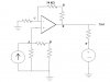
There's something I don't think I understand about node voltage analysis with ideal op amps. In the circuit shown below, At node D, I wrote the equation,
((1/1000) + (1/1000))Vd - (1/50000)Vc - (1/1000)Ve = 0
However my prof's equation for node D is:
((1/1000) + (1/1000))Vd - (1/1000)Ve = 0
I do not completely understand this. Unless me made an error. The only thing I could think of is something pertaining to the op amp's constraint Va = Vc, but if that justified getting rid of Vc in the above equation, it would seem like it'd justify getting rid of Va in the other ones, which he didn't do.
help?
Thanks alot;
Sean
EDIT: all resistors besides the one listed are taken to be 1000 ohms