Continue to Site

Welcome to our site!

Electro Tech is an online community (with over 170,000 members) who enjoy talking about and building electronic circuits, projects and gadgets. To participate you need to register. Registration is free. Click here to register now.

  • Welcome to our site! Electro Tech is an online community (with over 170,000 members) who enjoy talking about and building electronic circuits, projects and gadgets. To participate you need to register. Registration is free. Click here to register now.

Newbie : Need help to draw schematic based on this circuit !!

Status
Not open for further replies.
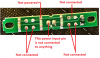
Since you are the only one with an actual module to look at, and you're in a hurry, what can you tell us about the LED that has no external connections? In the photos that are barely one day old (the ones in post #1 don't count) one of the LEDs has two pins connected together and two pins completely disconnected. And yet it lights ...

ak
 
We see only half of the wiring.
Instead of guessing about which connects to what, I would get out my multimeter and measure continuity. Can't you doo dat?
 

Attachments

  • LED thing.png
    LED thing.png
    147.1 KB · Views: 111
We see only half of the wiring.
Instead of guessing about which connects to what, I would get out my multimeter and measure continuity. Can't you doo dat?

I have uploaded the front side of the circuit ..if you look at it ..the middle connections are the source ( 13.5 v ) and I don't have power supply so I decided to use my drill battery to power them up .
IMG_0975.JPG
IMG_0986.JPG
 
This is a guess at that only..... At best, you have the physical board their.

That board has a top layer PCB track set and a Bottom.

The top has a coating that can hide as a silk screen process making the tracks hard or just plane impossible to see.

:Theories below:
 

Attachments

  • TOP.jpg
    TOP.jpg
    14.3 KB · Views: 108
  • Bottom.jpg
    Bottom.jpg
    77.2 KB · Views: 110
  • Overtransp.png
    Overtransp.png
    110.5 KB · Views: 111
  • Estimate.png
    Estimate.png
    19.1 KB · Views: 124
The image clipped out some text, that statement says at the left of the schematic that I am not too familiar with MELF Diodes even tho I have seen them on boards.
 
I think the OP might be correct. He thought the 3 resistors are in parallel 390//390//390=130 Ω. Then the 2 LED (actually 4 LEDs) are in series. Something like what he drew...

IMG_0984.JPG


and this is what I saw

IMG_0972.JPG


Green lines on component side and red lines on the LED side. (assuming double sided PCB)

Allen
 
It's easy to confirm. Just use an ohm meter and measure the parts linked by red line and see if there's any continuity...

Allen
 
I agree with the others, there do appear to be some hidden connections. It does not appear to be a 2-sided board, so I don't expect there are connections on the LED side, but there must be another layer somewhere (internal) that make the other connections. Based on the photos it is impossible to know for certain. You really need to buzz out the connections to see what is connected to what. Whoever laid out this board certainly didn't do it the way I would have done it....

My guess is that there is an internal V+ plane that connects the + side of the resistors in parallel. That doesn't explain why there aren't any visible connections to the top leads of the LED near R3. I would expect those to be connected to the top sides of the resistors, much like the LED between R1 and R2.
 
IMG_0972.JPG
top side_IMG_0986.JPG

If you look closely at the + and - 13.5V terminals and the LED terminals. You can see that it is a double sided PCB with plate-through holes.

Allen
 
If you look closely at the + and - 13.5V terminals and the LED terminals. You can see that it is a double sided PCB with plate-through holes.

Allen

I don't deny that there are plated through-holes but I don't see any indication of copper connections on the LED side. Normally you would see the slight protrusion of tracks, but I don't see that at all.
 
ok let me try to record a short video of the board ....maybe it easier to see all the connections on the the leds side .
I appreciate for all the inputs guys .
 
Ok here are the video .. it is a double sided pcb . You can actually see the lines going across from the led1 to led 2 .


Did you notice that for diodes or LEDs to be connected in series then the (-) of one connects to the (+) of the other one?
 
IMG_0990.JPG
I think the OP might be correct. He thought the 3 resistors are in parallel 390//390//390=130 Ω. Then the 2 LED (actually 4 LEDs) are in series. Something like what he drew...

View attachment 105215

and this is what I saw

View attachment 105216

Green lines on component side and red lines on the LED side. (assuming double sided PCB)

Allen
It's easy to confirm. Just use an ohm meter and measure the parts linked by red line and see if there's any continuity...

Allen

See attached
 
Can you confirm the red traces I've drawn on, taken from your continuity checks. Also when you say there is continuity please check its not a high impedance continuity and is ~0.1Ohm (some meters consider a 1K resistance as a connection)

Also please confirm which pin on the back in +V and answer the other point about the non-connected pins, do they go back to 0V?


IMG_09722.jpg
 
Instead of guessing about which connects to what, why don't you measure continuity with a multimeter?????
The resistors do not connect to both LEDs in between them, instead the other ends of the LEDs are connected in series.
 
Mr. absf, if you look at the datasheet for a Luxeon Superflux LED then you will see that it has one fairly high power single LED in a package that has 4 pins to disperse the heat.
 
IMG_1009.JPG
Can you confirm the red traces I've drawn on, taken from your continuity checks. Also when you say there is continuity please check its not a high impedance continuity and is ~0.1Ohm (some meters consider a 1K resistance as a connection)

Also please confirm which pin on the back in +V and answer the other point about the non-connected pins, do they go back to 0V?


View attachment 105226

See photos
 
IMG_1009A.JPG

IMG_0972_flipped.JPG

I flipped the bottom image 180° horizontally. Now the R1 + 1 and X1 all alligned with the top picture properly.

It should be correct this time.

Allen
 
Status
Not open for further replies.

Latest threads

New Articles From Microcontroller Tips

Back
Top