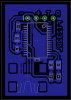
My latest PCB. I haven't had one made yet, will happily incorporate any constructive feedback before I sent it off. It is designed to meet the BatchPCB 2-layer rules.
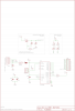
This implements a number of the features which are described in the FT232R datasheet. I/O voltage is selectable between 5v and 3.3v using the jumper at the top. All serial port pins are exposed to a breadboard through the connector.
LEDs are available to show the status of RX and TX (the chip has a circuit built-in to ensure these are seen even with a brief data transfer).
USB power is provided to the circuit through the 5v connector using a slow start circuit as suggested by the datasheet. This is apparently programmable up to 500mA.
I'm looking forward to testing this chip. The potential of USB (with all versions of Windows and modern Linux kernels) with USB power is quite appealing.
**broken link removed**
**broken link removed**
This is my first entirely SMD board. Constructive feedback most welcome.
")