Continue to Site

Welcome to our site!

Electro Tech is an online community (with over 170,000 members) who enjoy talking about and building electronic circuits, projects and gadgets. To participate you need to register. Registration is free. Click here to register now.

  • Welcome to our site! Electro Tech is an online community (with over 170,000 members) who enjoy talking about and building electronic circuits, projects and gadgets. To participate you need to register. Registration is free. Click here to register now.

Need Info On A Bias Setting **help**

Status
Not open for further replies.

BassNGuns

New Member
Hi,
I have to replace the output tranny's on an old Acoustic PA 120-6 amplifier
and don't know what the bias setting needs to be.
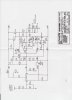
I'm attaching the schematic and wanted anyones opinion on whether the .7 VRMS
listed on this was what they were reffering to.
The schematic says model 123, but it's supposed to be the same curcuit.
I've tried different forums and have gotten no response as to what the setting may be or the test points.
--Thanks.
 

Attachments

  • Acoustic 123 001.jpg
    Acoustic 123 001.jpg
    661.8 KB · Views: 351
Last edited:
The 0.7 VRMS is the amount of AC signal applied to the input of the amplifier to give you full output - 100 Watts into 4 ohms in this case. The bias in this circuit is used to set the crossover point at which the PNP and NPN output transistors conduct. If they conduct at the same time, there will be current draw with no input signal and they will destroy one another. If they conduct too far apart, you will have a distorted sine wave. To adjust, apply a minimal amplitude sine wave (maybe 0.1 VRMS) at say 1 Khz to the input and adjust the bias until there is no space between the positive and negative peaks of the output signal.

I would recommend using a reduced power supply voltage (using a variable transformer), or at least insert very small fuses in series with the both the positive and negative supplies. If the bias is too far off, the output transistors will destroy themselves in milliseconds! And don't forget to load the output with a 4 ohm load. Output transistors don't like open circuits.
 
The trimpot P1 adusts how much idle current flows in the output transistors to reduce or eliminate crossover distortion.
If the current is too low then the output transistors operate in class-B. You want them to operate in class-AB which is a current of 30mA to 60mA in each output transistor which you can calculate if you measure the DC voltage across the emitter resistors for the output transistors.

Connect your 'scope to the output to see about 2V p-p with a sine-wave input to the amplifier to see if there is any crossover distortion.
Crossover distortion looks like this:
 

Attachments

  • crossover distortion.PNG
    crossover distortion.PNG
    14.5 KB · Views: 334
Status
Not open for further replies.

Latest threads

New Articles From Microcontroller Tips

Back
Top