Continue to Site

Welcome to our site!

Electro Tech is an online community (with over 170,000 members) who enjoy talking about and building electronic circuits, projects and gadgets. To participate you need to register. Registration is free. Click here to register now.

  • Welcome to our site! Electro Tech is an online community (with over 170,000 members) who enjoy talking about and building electronic circuits, projects and gadgets. To participate you need to register. Registration is free. Click here to register now.

need help with TSOP 1738 sensor

Status
Not open for further replies.

niraj_khandekar

New Member
hey ppl,
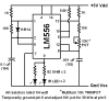
i am currently working on a micromouse withits base sensors as TSOP. bt the problem is tht they arent responding tht well to the 555 timer - 38khz transmitter tht i made. can u guys give me a lil information on da working of TSOPs. and can tsops be directly connected to an ADC. the response was very haphazard. it wasnt constant and kept fluactuating.

thank you
 
hey dude, i hav the datasheet. i generated 38khz using the 555 timer. i saw all the graphs. but it isnt working. ill be thankful if u try to elaborate a few points. firstly can i attach the output of tsops to ADCs cus it keeps on fluctuating, secondly do u no of ne other transmtter circuit which works best. ma only concern is the voltage variation, not range. presently im getting 20 cms and that is good enough for me. im using 555 in astable mode, with a diode across Rb so tht discharging is based on Ra only and i get a square wave.

thank you
 
I would suspect the 555 based transmitter circuit rather then the well designed TSOP part.

I recall that the TSOP expects transmission bursts. Do not send it a continous IR stream.

Have you looked at the TX and RX outputs on a scope ?
 
i havnt checked it on the osciloscope as of nw. im attaching da schematics of the circuit. plz tell me if theres any thing wrong with it.**broken link removed**

i have put a diode across resistor R2 to get a square wave waveform.
values are:
R1 = 180Ω
R2 = 200Ω
c = 0.1µF

also tell me does is there any optimum postion in which the sensors should be placed for perfect reception.

does it matter if i dont get exactly 38Khz frequency. will it affect the reception of TSOP?
 
and 1 more thing, what exactly are transmission bursts. from wat i interpretted, i think the are it is a varying voltage with a particular frequency. am i correct??
 
Like colin mac said, your 555 timer gives just below 25khz. Try:

C = 10nf (0.01uF) ten times smaller than you have now
R1 = 1.8k
R2 =1k

These should be very easy to find (all are standard E12 values) and give 37.97kHz. The TSOP has a very narrow response bandwidth, you need to be at 38kHz +/- a kHz or two at most.

Question for the forum: does duty cycle matter at all in this application? I should think it gets lowpassed by the sensor and it wouldn't matter, but I might be wrong.
 
Last edited:
and 1 more thing, what exactly are transmission bursts. from wat i interpretted, i think the are it is a varying voltage with a particular frequency. am i correct??
Nope. A burst is just a short transmission or msg. Remotes generaly send a device address and code. That is more info then you are interested. What you need to know is that is quickly sends it msg and then turns off. The TSOP is designed around this behavior. If you transmit for too long it confuses your transmission with stray light and the TSOP will not work as well. You need to turn on your transmitter for short periods of time.

Also you may be able to test the TSOP reciever with a TV remote.
 
You could adapted this you can adjust it down to 38khz
 

Attachments

  • beacon.PNG
    beacon.PNG
    19.5 KB · Views: 1,848
i got the tsop to work correctly, but the readings that im gettin keep on fluctuating. for instance, i hav a perfectly smooth obstacle placed at say 8 cm distance, the output voltage tht im gtn should be constant lyk 2.3 volts.. but it keeps on fluctuating between 2.7 to 2.1 volts.. hw is da ADC supposed to convert such fluctuating voltage. and evn if it manages to convert it, the the programmin wud becme faulty because of the varying ADC output....
 
Exactly which TSOP part are you using. The ones I am thinking about are digital and output +5 with on activity and 0V when modulated IR is present.
https://www.electro-tech-online.com/custompdfs/2008/12/tsop362x.pdf

It sounds like you are talking about a distance sensor with an analog output like the ones built by sharp.
**broken link removed**

Give us a link to your datasheet.
 
I missed that you specified the part in the post title. My bad.

i got the tsop to work correctly, but the readings that im gettin keep on fluctuating. for instance, i hav a perfectly smooth obstacle placed at say 8 cm distance, the output voltage tht im gtn should be constant lyk 2.3 volts.. but it keeps on fluctuating between 2.7 to 2.1 volts.. hw is da ADC supposed to convert such fluctuating voltage. and evn if it manages to convert it, the the programmin wud becme faulty because of the varying ADC output....

I do not understand why you are hooking the TOSP to an ADC input. Are you trying to do IR communication or measure how far an object is away.

If it is about IR communication
take a look at nigel's tutorial 5 it is about IR communication.


If you are trying to detect objects or measure distance you have the wrong part.
 
rutvik here,
i m using the device for measuring the distance.
So is it a correct device ?????
Becoz i m getting a variable output when receiving the signal through a tsop when checking with a multimeter.....

And what is the optional device recomended by you for distance measurement...???????
 
Last edited:
* plz recommend any sensor except the sharp sensors.. cus they arent easily available.. recommend a sensor tht gives variable output.. eg the voltage drops as the distance decreases and visa versa.
 
If you could look at the TSOP output with a scope you might see that it is outputing 0 and 5 V pulses. Your meter is averaging them so it only looks like analog.

Regardless the TSOP is a part intended to recieve IR codes from a remote control (TV). It is not intended to measure distance.

I have only used the sharp parts. Maybe someone else can thing of others. You can check the robotic web sites and online stores to see what else is out there. Google.

3v0
 
The Sharp & Vishay IR demodulators are pretty near interchangeable. All are digital out and all have AGC (so you can't send a constant stream on IR data to them, only short bursts)
 
I want to make ir sensor using tsop to detect object and i am using 555timer circuit to generate 38khz in transmmitting part but my ir led donot give output plz give me proper circuit
 
Status
Not open for further replies.

Latest threads

Back
Top