Electro Tech is an online community (with over 170,000 members) who enjoy talking about and building electronic circuits, projects and gadgets. To participate you need to register. Registration is free. Click here to register now.
Welcome to our site! Electro Tech is an online community (with over 170,000 members) who enjoy talking about and building electronic circuits, projects and gadgets. To participate you need to register. Registration is free. Click here to register now.
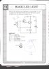
I have built this circuit 3 times, I havn't found anything wrong with it, but the LED stays on all the time. I was hoping that one of you guys can find something wrong.
Tell me what do you think it is doing in this circuit?
Answer.. NOTHING.
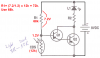
Q2 Emiter, has constant access to Positive and the Base of Q1 has its negative. Your circuit is always On as long as the base of Q1 is negative, So your CDS should be in series from Base of Q1 to R1. And R1 should not be directly connected to Base of Q1.
Tell me what do you think it is doing in this circuit?
Answer.. NOTHING.
Q2 Emiter, has constant access to Positive and the Base of Q1 has its negative. Your circuit is always On as long as the base of Q1 is negative, So your CDS should be in series from Base of Q1 to R1. And R1 should not be directly connected to Base of Q1.
If I understand you correctly, you propose having the CDS and R1 in series, from base of Q1 to the negative terminal of the battery. This won't work. The Darlington beta will be so high that the LED will never turn off.
Audioguru shows the right way to do it. The only thing wrong was the value of R1, although the value of R2 (100 ohms) is going to allow about 50 or 60 ma to flow through the LED. A safer current level for most LEDs is about 10 - 20 ma. I would make R2=300 ohms or greater.
The only thing wrong was the value of R1, although the value of R2 (100 ohms) is going to allow about 50 or 60 ma to flow through the LED. A safer current level for most LEDs is about 10 - 20 ma. I would make R2=300 ohms or greater.
Awwww! You spoiled it. :cry:
I wanted him to smoke his LED and learn about having too much current the hard way. 60mA continuously through an LED would look spectacular (for about 5 seconds)!
A 9V battery is mosly wasted when powering a 2V LED. A 9V battery has 6 tiny AAAA cells inside so doesn't have much capacity to waste any.
Therefore I would use three alkaline AA cells in series to power the circuit. When they are new, the LED current will be 26mA for a red LED or 13mA for a white or blue one. When the cells' voltage drops to 1V each at the end of their life, a red LED will have about 12mA and a white or blue LED about nuthin'. Three C or D cells could be used for much longer life.
R1 should be changed to 27k or 33k when a 4.5V battery is used. :lol:
Awwww! You spoiled it.
I wanted him to smoke his LED and learn about having too much current the hard way. 60mA continuously through an LED would look spectacular (for about 5 seconds)!
Im confused. Why would the ckt not work. If the resistance of the CDS falls to 3k as stated in the diagram wont the base be at a positive potential hence causing the darlington pair to become inactive.
If you look at both the above circuits they form voltage divider working on the same principle. We may need to simply change the value from 4.7K to 10K to provide a higher tolerance
There is only one battery. The emitters are connected to the positive terminal. There is no way the base can be more positive than the emitters.
Look at AudioGuru's drawing. It is easier to understand, and is the same topology. You are correct in saying that they form a voltage divider, but 10k will not solve the problem. 68k will. Of course, if you use 4.5V, you have to change the value of R1, as AudioGuru pointed out.
This site uses cookies to help personalise content, tailor your experience and to keep you logged in if you register.
By continuing to use this site, you are consenting to our use of cookies.