Continue to Site

Welcome to our site!

Electro Tech is an online community (with over 170,000 members) who enjoy talking about and building electronic circuits, projects and gadgets. To participate you need to register. Registration is free. Click here to register now.

  • Welcome to our site! Electro Tech is an online community (with over 170,000 members) who enjoy talking about and building electronic circuits, projects and gadgets. To participate you need to register. Registration is free. Click here to register now.

Motor turned too much (H-bridge related)

Status
Not open for further replies.

menirva

New Member
I managed to build a h-bridge to drive a motor forward/backward. But the problem now, the motor turned forward/backward too much.

This motor is for robot one leg movement (forward/backward), so i need a nice movement/motor turn suitable for leg movement. My idea is to give a signal as shown in the attached picture.

forum7.GIF

I have not try it. Will this be okay? Or is there any nicer idea?

p/s: i use dc motor
 
I just noticed the attached signal will not work too, because of the T_low being longer, thus will make motor turn anti-clockwise longer..

anyone have any idea how to solve this? or just increase frequency?
 
This is for a leg? Can you just use an RC servo motor? If not, you need position feedback on your H-bridge so the microcontroller knows the absolute position of the motor. It's not good enough to guess since the load changes on the motor and it will travel by different amounts for the same input signal.
 
Could you post a schematic? An H-bridge requires two logic signal inputs. Your display shows only one. And your comment about "long T-low" driving it anti-clockwise, sounds like you are trying drive it with an R/C servo signal.

Ken
 
i think if u'd like to generate signal like this u must use the PWM
Put a SCH or descripe the project
 
There's a reason why i construct the oscillator like this.. The waveform shows the output which i connect to both the H-bridge input signal.

forum1.GIF And this type of signal which i currently connect to both H-bridge input signal.


Below attached signal is the waveform that i'm currently try to figure out how to get it. With this, there will be a time where both input to the H-bridge is LOW, therefor the motor will not turn for a moment.

forum2.GIF

I'm not really going to build a whole robot, just a circuit which can make a motor turn clockwise and anti-clockwise, to represent the leg hips joint movement. I'm doing this with no microcontroller, just with electronic component. I just have a common dc motor.
 
Last edited:
If you aren't actually going to build the robot, and it looks indeed as though you aren't since your schematic shows no inputs, then just use an 555 to alternate the direction of the motor.

However, upon re-reading your post, I see this will not work, since you want the robot to pause in between switching directions. So what you should do is use TWO staggered 555 oscillators.

Hopefully I am understanding what you want.
 
If your Stop time can be equal to your Forward and Reverse times, then maybe you can use an 8-bit walking ring counter with OR'ed outputs.

Ken
 

Attachments

  • Alternate Pulse.gif
    Alternate Pulse.gif
    19.2 KB · Views: 323
KMoffett said:
If your Stop time can be equal to your Forward and Reverse times, then maybe you can use an 8-bit walking ring counter with OR'ed outputs.

Ken


I will try this. Can 74HC390 substitute the CD4022? Because now i have 74HC390 counter. For the diode, can i use 1n4001, or 1n4007?
 
Last edited:
The 74HC390 is a "ripple counter" doing a binary count on the outputs. The 4022 is a "walking ring counter", with only one output high at a time. Compare the datasheets. They cannot replace each other. The diodes are 1N4148, but any 1N400x would work. Not knowing anything else about your circuit I would make the resistors 10K.

Ken
 
I design my h-bridge with PNP 2N3906, and NPN 2N3904. When i touch the transistor, it is very hot. The current flow the transistor is around 2A (darlington pair). I fear this may burn the transistor.

What other transistor model that suit to substitute my currently used transistor? Preferable cheap, and easy to get (common used). I'm very new to transistor usage, before this i just know how to use transistor.
 
Please post a schematic of your 2N3904/2N3906 circuit.

Ken
 
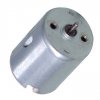
forum3.GIF This is my current configuration for h-bridge. The dc motor that i use looks somewhat like this. DC_Motor.jpg

Is there any other way to substitute the CD4022? I just went to nearest electronic shop, they got no stock anymore for this component.
 
Bill has it...a 4017!

Your 2N3904s and 2N3906s have a "absolute maximum" collector current rating of only 0.2A. The 2N3703 has a max of 0.5A. Hooking them up as a darlington gives you current gain, but you still can't exceed 0.2A to drive the motor. Difficult to recommend correct transistors if you are only shopping locally and we don't know what they have. You need to look for output transistors, Q48/50 and Q57/59, with collector current (Ic) ratings higher than 2A. Also plan on heat-sinking them.

Ken
 
Last edited:
I build two h-bridge, both share the same voltage source (6VDC). Result is, the current output to drive a motor (one motor for each h-bridge) is so small.

Can someone give me some idea, how to drive two motor, without using so much voltage source? 1 voltage source for driving 1 motor, not really good in my opinion.
 
Is your supply voltage for the h-bridge only 5V?
Then if you use 2A darlington transistors like the TIP110 and TIP115, the motor will receive no voltage when the darlingtons have their max allowed saturation voltage loss. But then the motor wouldn't use any current so the saturation voltage loss will be less than 5V but might be as high as 3V so the motor gets only 2V.
 
KMoffett said:
If your Stop time can be equal to your Forward and Reverse times, then maybe you can use an 8-bit walking ring counter with OR'ed outputs.

Ken

What best to describe this circuit? A "what" circuit? What name best fit it?
 
menirva said:
I build two h-bridge, both share the same voltage source (6VDC). Result is, the current output to drive a motor (one motor for each h-bridge) is so small.

Can someone give me some idea, how to drive two motor, without using so much voltage source? 1 voltage source for driving 1 motor, not really good in my opinion.

Sounds like your supply voltage is too low, use relays instead of transistors, you can't PWM but you get pretty well zero voltage loss to the motor.

Or use a DPDT relay for reversing, and a single transistor (or FET) for PWM.
 
Even if TIP110 and TIP115 complimentary darlington transistors are used to drive the motor with up to 2A from a 6V supply, their saturation voltage will reduce the voltage of the motor to from 1V to 4V.
 
Status
Not open for further replies.

New Articles From Microcontroller Tips

Back
Top