Continue to Site

Welcome to our site!

Electro Tech is an online community (with over 170,000 members) who enjoy talking about and building electronic circuits, projects and gadgets. To participate you need to register. Registration is free. Click here to register now.

  • Welcome to our site! Electro Tech is an online community (with over 170,000 members) who enjoy talking about and building electronic circuits, projects and gadgets. To participate you need to register. Registration is free. Click here to register now.

Momentary pulse LED sequencer circuit.

MikeBer

New Member
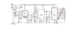
I have a circuit that works perfectly. When the normally closed switch is pulsed, the LEDs sequence from 1 to 9 and then the circuit resets and switches off the LEDs. This works using a 4013 flip flop. (fig. 1).
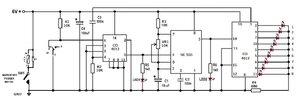
However, I now need the circuit to work with a normally open trigger switch. I can do this by adding an additional relay. It's normally closed contacts replace SW1 and when the relay is energized, the contacts break and trigger the sequencer circuit. (fig 2).
My question is, is it possible to re-configure the 4013 to trigger with a normally open switch, obviating the need for the additional relay?

Any help would be much appreciated.
 

Attachments

  • fig.1 - 9 LED sequencer N-C schematic.jpg
    fig.1 - 9 LED sequencer N-C schematic.jpg
    138.5 KB · Views: 144
  • fig.2 - 9 LED sequencer N-O switch schematic.jpg
    fig.2 - 9 LED sequencer N-O switch schematic.jpg
    143.9 KB · Views: 122
It might be as simple as moving around parts.

As it is now, the NC SW1 holds the Set input low, and pressing the switch allows R1 to pull the Set input high for as long as the switch is held.

To make your change, swap the positions of R1 and the now NO SW1. Now, R1 holds the Set input low when SW1 is open. When SW1 closes, it pulls the Set input high for as long as the switch is held.

ak

Black dot - One of the flipflop outputs is shorted directly to GND.

Gold star for the use of reference designators. Tiny nit - to prevent confusion, rename the new switch SW2. There is no hard-and-fast rule about the first component type in every schematic starting with xx1. Some companies require notation of unused, last-used, and/or non-sequential reference designators, but that seems to be fading away.
 
Just as a consideration for future designs this can be done in 1 chip

1) Arduino 328P in dip package. Use Uno dip version board to dev and program dip, ~$5

2) Or just use a Nano board, ~ ($ 2 - 3). For dev and final actual design.

1690206836840.png


This is mBlock, a block programming language where you drag and drop functional blocks, config them,
and mBlock converts that to Arduino code for you and programs dev board. Board to use is Nano, ~ $3,
or if you want to use dip chip dev board to use is Uno.

mBlock and the Arduino program IDE are free.

Advantage is timing much more exact, if Nano board used < .1% error or just chip +/- 10%. Or 1%
simple user cal routine for dip. I set LED on time for 1 sec/LED, that can be anything from 1 mS to
years. Just changing the config value for the LEDonTime variable.

1690207797624.png


Only external components, LEDs, switches, 1 R for each LED, and a cap to bypass Arduino chip (not needed if using
Nano board). Nano board has a regulator on it. You also need a pullup and pulldown R for appropriate switch.

The solution in right hand window is correct for design I think, and handles both switches.

Project attached in case you want to look at it in mBlock.


Regards, Dana.

PS : I missed LED1 and LED2 in your schematic, that would be easy to add them as well.
 

Attachments

  • Sequencing 9 LEDs.zip
    56 KB · Views: 104
Last edited:
With a 6V supply, the low current from a CD4017 produces dim LEDs.
For my LED chasers, I use a 6V supply and blink each LED for, a moment to save battery power.
For much higher brightness than a CD4017, I use a 74HC4017 Cmos IC and limit its output current with a resistor to less than its max allowed 25mA.
Here is the low current from a CD4017:
 

Attachments

  • CD4017 output current.png
    CD4017 output current.png
    180.8 KB · Views: 102

Latest threads

New Articles From Microcontroller Tips

Back
Top