Continue to Site

Welcome to our site!

Electro Tech is an online community (with over 170,000 members) who enjoy talking about and building electronic circuits, projects and gadgets. To participate you need to register. Registration is free. Click here to register now.

  • Welcome to our site! Electro Tech is an online community (with over 170,000 members) who enjoy talking about and building electronic circuits, projects and gadgets. To participate you need to register. Registration is free. Click here to register now.

Mini Guitar Amp schematic question

Status
Not open for further replies.

h3d

New Member
hi all, i have recentley found a guitar amp schematic on redcircuits.com and i have built it (its working!!), but i have two questions:-

**broken link removed**

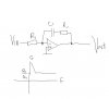
1) capacitors C2, and C3; what are they for? I have taken them out of my circuit and it makes no difference to the sound??!? it says to connect them to ground (in the diagram) so i have linked them to the negative terminal on my 9Volt standard battery. Am i connecting these correctley?

2) what is capacitor C1 for!?! i have done the same as the above and taken it out of the circuit, and NOTHING changes?!?!

is there a better place online for me to be asking these questions? If so please post, thankyou in advance for any replies :lol:
 
C1 is an audio coupling capacitor to strip the audio in of any DC and leave the remaining AC. If the input is already AC or has a very small DC then removing this will have no noticeable effect.

Also the combination of C1 and R1 form a Passive high pass filter, which will gradually diminish any frequencies less than (1/2*pi*R1C1) from the input being passed through the circuit.

C2 and C3 look like supply decoupling capacitors, that means in the event that the circuit starts loading the supply and its voltage drops, the rail is held by the capacitors so its kept rigid and fixed.

Megamox
 
You should fit the capacitors, as already suggested C1 is a coupling capacitor, and you will very likely have problems without it? - if you're using an active guitar then there might be one in the guitar?, but in any case you should add it!.

The other two (also as suggested) are supply decoupling capacitors, you could perhaps leave the small one out? (it's only there as an extra precaution), but the large electrolytic is required - without it you will have stability problems, and greatly reduced battery life.
 
hey cheers for the ULTRA FAST response guys, ive never received such a quick reply before. I have bought all of the above components and so i will take your advice and fit them all :D. One more question,

any ideas on how i would effectivley "boost" the bass output to the speaker?
 
The only way i know how to bass boost a signal is by using an active filter. With op-amps, put a capacitor C1 and resistor R1 in series in the feedback loop of an inverting configuration, and a resistor R2 on the inverting input(-). Put the non inverting(+) input to ground. The gain of the Amp is -(Loop impedance/Impedance from Vin to Inverting input). At Low freq (BASS) the reactance of C1 is large, so Gain = -Large/Constant R2 = Large = Boost. At high Freq Reactance of C1 is low, Feedback Loop resistance becomes ~ R2 as C1's reactance becomes negligible. So Gain = -R1/R2 = fixed. If you dont want any treble Gain, make this ratio unity. This is all off the top of my head i think its all correct.

Megamox
 

Attachments

  • bassboost.jpg
    bassboost.jpg
    15.7 KB · Views: 1,241
will op amps give me as good a quality as the TDA? i tried the schematic above and as soon as R2 hits one of my two outputs (to the speaker) the sound cuts out all together. Does this mean that the chip will not allow me to do it in this way (i take it it does)?

Also, if i got a 4 ohm speaker (instead of the existing 8 ohm) would this effectivley double the circuits maximum output (RMS).

Sorry about the r*tarded questions :oops:
 
You need to match the impedances into the circuit. R2 represents your input impedance of your bass boost amp. R2 needs to be big so you're feeding the signal into a high impedance. Something of about 1M. R1 needs to be chosen so that the ratio R1/R2 gives the correct treble Gain. And C1 needs to be chosen for the cut off point of the filter --> 1/(2*pi*R1*C1). Follow the output of this circuit with an op amp wired as a voltage follower and maybe add on a push pull transistor config to supply the current before u attach it to a speaker.

Megamox
 
Follow the output of this circuit with an op amp wired as a voltage follower and maybe add on a push pull transistor config to supply the current before u attach it to a speaker.

ah, so this will boost the volume?
 
No that just isolates the output of the amp so that providing the signal to the speaker doesnt corrupt it. Volume control can be achieved with a variable resistor in series with the speaker.

Megamox
 
Your little TDA IC is rated for only about 1W into an 8 ohm speaker. A 4 ohm speaker would overload it because it would try to produce 2W into it.

Since the circuit boosts the bass then the volume control must be turned down by the same amount because the amp doesn't have enough extra power output to allow boosting.

Audio opamp circuits must have a negative feedback resistor for DC.

Is this what you want?
 

Attachments

  • bassboost.png
    bassboost.png
    38.9 KB · Views: 700
Status
Not open for further replies.

New Articles From Microcontroller Tips

Back
Top