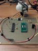
No car batter, lol. But I do have an 18.4V drill battery I can give a shot. But I neet to make sure first that the code I have is also fine. I think I might need to add some pull-up, pull down, resistor to the logic signals. One thing I should change is the wires. I'm using really thin wire in the protoboard, like 32GWA for the 12V and power ground. I will change those to 22GWA and see if that helps.
Last edited: