Continue to Site

Welcome to our site!

Electro Tech is an online community (with over 170,000 members) who enjoy talking about and building electronic circuits, projects and gadgets. To participate you need to register. Registration is free. Click here to register now.

  • Welcome to our site! Electro Tech is an online community (with over 170,000 members) who enjoy talking about and building electronic circuits, projects and gadgets. To participate you need to register. Registration is free. Click here to register now.

Manual SN74LS165

Status
Not open for further replies.

AtomSoft

Well-Known Member
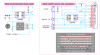
Hey i got a theory again... Using this SN74LS165 "8-Bit Parallel-to-Serial Shift Register" i want to have buttons connected to it to turn my signal into a digital signal by it sending the serial data to the pic from the 8 parallel inputs. Heres how i think it would work...

From Datasheet:
"For clock operation, PL must be HIGH. The two clock
inputs perform identically; one can be used as a clock inhibit
by applying a HIGH signal. To avoid double clocking,
however, the inhibit signal should only go HIGH while the
clock is HIGH."

so i can set the CP1 & CP2 at the same time with a transistor(or 2).

Then i read:
Parallel data enters when the PL signal is LOW. The parallel data can
change while PL is LOW, provided that the recommended
setup and hold times are observed.

Meaning i should set the PL high when changing the Parallel data. (unless i follow timing)

So i would set PL high (pull up High) with a transistor which is triggered from a pullup to VCC so its always high until i press button which triggers the transistor to connect VCC to CP1 & CP2 and another transistor to tie GND to PL this way when i press the button this happens:

CP1 = HIGH
CP2 = HIGH
PL = LOW
Px (parallel pin x) = High

when no button pressed:

CP1 = LOW
CP2 = LOW
PL = HIGH
Px (parallel pin x) = LOW

If i have 4 buttons then if i press the third button it should send the above(you know which one) and the Serial out should then be

3rd button
HIGH NYB - LOW NYB
0000 - 0100


2nd button
HIGH NYB - LOW NYB
0000 - 0010


1st button
HIGH NYB - LOW NYB
0000 - 0001


4th button
HIGH NYB - LOW NYB
0000 - 1000


Understand? I havent done it its theory .. do you think it would work?
 
so i can set the CP1 & CP2 at the same time with a transistor(or 2).
Just set one of them low and use the other as the clock input from the PIC.
Meaning i should set the PL high when changing the Parallel data. (unless i follow timing)
Momentarily pulse PL low to load the switch data into the 74LS165.
Set PL high when you clock the 8 bits out by pulsing CP1 or CP2 with the PIC. The data comes out pin 9.
 
So when waiting for input( normal or released)
PL = HIGH (or LOW TO HIGH (from release))
CP1 = LOW (tied low)
CP2 = LOW (or LOW to HIGH(from release))
Parallel Pin = LOW

when button Pressed
PL = LOW
CP1 = LOW
CP2 = HIGH
Parallel Pin = HIGH
 
Are you putting these switches on the same project that uses the 2 wire 74HC164 or 74HC174 LCD controller?
 
Last edited:
Do you want the PIC to poll the switches via the 74LS165? If so, then only one CP pin, the PL pin, and pin9 (serial out) need be connected to the PIC and are under the PIC's control at all times.
 
Just set one of them low and use the other as the clock input from the PIC.

Momentarily pulse PL low to load the switch data into the 74LS165.
Set PL high when you clock the 8 bits out by pulsing CP1 or CP2 with the PIC. The data comes out pin 9.

Ok i understand the setting of the CP1 low and just controlling the CP2.

You lost me on the second part tho.

Should i set the set PL low then high(pulse) and then clock it in(pulse CP2)?


MIKE:
YES :D im trying to conserve pins. :D
 
Last edited:
Well if you're using a '174 or '164 for the LCD interface you might consider using those four latched LCD outputs to drive a switch matrix. You would use one additional pin on the PIC to read the switches. Let me know if you need details...

Mike
 

Attachments

  • 164 LCD Interface.PNG
    164 LCD Interface.PNG
    46.3 KB · Views: 263
Last edited:
Well if you're using a '174 or '164 for the LCD interface you might consider using those four latched LCD outputs to drive a switch matrix. You would use one addition pin on the PIC to read the switches. Let me know if you need details...
I like it! I've been about to start designing and etching a 2-wire LCD board (or two) for a week or two now. Maybe I'll steal your design there and add some buttons and maybe even that temp sensor. So convenient to be able to connect an LCD so easily and quickly to any MCU. Breadboarding it takes all the convenience and quickness out of it. :p
 
Last edited:
mike im afraid you are going to lose me here lol if you can explain more then shoot.

I think i understand the 165 way.

I Toggle the PL line to set the new data.
I loop 8 times each time clocking and reading the DS pin.

Right?
 
hey hey i was thinking about making it too! you theif lol just kidding. But to make one should be childs play even with a prefboard aka Radio Shack crap would be good lol.

I took a HDD cable and cut it off and soldered it to that red SMD board from DipMicro and have my GLCD plug in it :D ill take a pic one day...(camera needed of course lol) ill check tomorrow for it though
 
Last edited:
Should i set the set PL low then high(pulse) and then clock it in(pulse CP2)?
Yes.
Setting PL low loads the 8bits into the shift register and disables clocking. Once it goes high, the 8bits are "stored" and are ready to be clocked out.
 
The procedure for reading the switch matrix on the latched outputs of the 2 pin 74HC164 interface is relatively simple. Here's an "untested" example;

Code:
void lcd_buttons()              // read LCD switch matrix
{
  char i;
  data = 0;                     //
  for(i=0; i<6; i++)            // clock out six '0' bits
    clock = 1; clock = 0;       // to clear the '164 latches
  data = 1;                     //
  clock = 1; clock = 0;         // col 0, '0001' (QA = 1)
  data = 0;                     //
  i = 0;                        //
  if(swpin == 1)                // if SW1 on Q1 pressed
    i.0 = 1;                    //
  clock = 1; clock = 0;         // col 1, '0010' (QB = 1)
  if(swpin == 1)                // if SW2 on Q2 pressed
    i.1 = 1;                    //
  clock = 1; clock = 0;         // col 2, '0100' (QC = 1)
  if(swpin == 1)                // if SW3 on Q3 pressed
    i.2 = 1;                    //
  clock = 1; clock = 0;         // col 3, '1000' (QD = 1)
  if(swpin == 1)                // if SW4 on Q4 pressed
    i.3 = 1;                    //
  i ^= SwLatch;                 // changes (press or release)
  SwLatch ^= i;                 // update switch state latch
  i &= SwLatch;                 // i = "new press" bits
  SwFlags ^= i;                 // update flag bits for Main
}
BTW, I use the latched outputs on my little 1 pin 12F635 serial LCD interface the same way (drawing below). It works great (1 pin for the LCD and 1 pin to read the switches).


You can also connect a 3x4, 4x4, or 5x4 keypad to the latched outputs but this would require 3, 4, or 5 PIC pins, respectively, to read the switches.

Happy Holidays everyone.

Mike
 

Attachments

  • 12F635 LCD Interface.PNG
    12F635 LCD Interface.PNG
    73.3 KB · Views: 144
Last edited:
Using the 165 i tried the below but i get a constant 0x34 with or without buttons pressed:
NOTE: I have DS = DATA STATE not Serial Data Input. I have DS connected to Q7

Code:
char readPL(void){
    char x;
    char buff;

    PL=0;
    delay_us(1);
    PL=1;

    for(x=0;x<8;x++){
        buff <<= 1;             // shift composed byte by 1
        buff &= 0xFE;           // clear bit 0

        CP2=0;
        delay_us(1);
        CP2=1;

        if (DS)                 // is data line high
            buff |= 0x01;       // set bit 0 to logic 1
    }
    return buff;
}

Also i setup the PINS as such:
Code:
#define PL  LATBbits.LATB0
#define CP2 LATBbits.LATB1
#define DS  PORTBbits.RB2

#define PL_T  TRISBbits.TRISB0
#define CP2_T TRISBbits.TRISB1
#define DS_T  TRISBbits.TRISB2
and
Code:
    PL_T = 0;
    CP2_T = 0;
    DS_T = 1;
 
Last edited:
I change wiring now it stays as 0xDD but

Button00 works and Button05

When i press Button00 the 0xdd changes to : 0xDF
so from
11011101(0xDD)
to
11011111(0xDF)
which is bad since button00 is on P0 not P1

and when i press Button05 it changes to 0xFD
so from
11011101(0xDD)
to
11111101(0xFD)
Which is also bad its on P4 not P5
 
Last edited:
Jason,

Which 74LS165 device Data Sheet are you using? I'm lookin' at the TI 74HC165 Data Sheet which seems to be different (doesn't have two PL pins)?

Mike
 
Ok i fixed that off point thing like PIN0 == button 0 now i had to get data then clock
Code:
char readPL(void){
    char x;
    char buff;

    PL=0;
    delay_us(100);
    PL=1;

    for(x=0;x<8;x++){
        buff <<= 1;             // shift composed byte by 1
        buff &= 0xFE;           // clear bit 0


        if (DS)                 // is data line high
            buff |= 0x01;       // set bit 0 to logic 1

        CP2=0;CP2=1;
    }
    return buff;
}

But only Button00 and Button05 work. All are setup the same way and i tried another 165 in-case it was damaged but no luck.

I have the Serial In Tied to GND

I should mention its a TI(texas instr...) SN74LS165AN
 

Attachments

  • 165.pdf
    199.1 KB · Views: 271
I'm sorry, I meant two CP pins.

Anyway it looks like you're heading in the right direction. The D7 bit shows up on the output before you start shifting data.

Mike
 
Last edited:
i still need to shift 8 times because im collecting 8 bits. The 1st bit just comes before the first clock then the other 7 shifts in.

The issue is i can only get P0 and P5 correctly the rest dont work at all. Im not sure why but its upsetting. :(
 
Status
Not open for further replies.

Latest threads

New Articles From Microcontroller Tips

Back
Top